C6 overhaul, Building a Dominator


#17
 05-06-2014, 08:13 PM

#20
05-06-2014, 11:04 PM
There are different levers with different apply ratios. The reason I asked is because you do not want to run a R code servo with an F or H lever (too much apply force.)
#23
05-07-2014, 07:03 AM
The trans in my truck has a D servo with an E lever, before I put the wide tires on the back it would go sideways and go all the way around if I didn't lift when it shifted into 2nd gear. Some people opt to use an F lever with the smaller servos because it provides a solid 1-2 shift and costs about 1/3 of the price of an aftermarket R servo.
Here are the C6 intermediate servo specifications:
CODE ON COVER, APPLY DIA, RELEASE DIA, SEAL TYPE
From softest to firmest shift…:
N 1.93-2.92 Molded piston
S 2.00-2.86 Molded piston
G 2.04-3.02 O-rings
J 2.07-2.69 O-rings
L 2.07-2.98 Molded piston
D 2.08-2.98 O-rings
P 2.10-2.86 Molded Piston
H 2.34-3.02 O-rings
R 2.48-3.50 O-rings
Here are the C6 servo apply lever ratios:
From least to most apply force…:
A = 1.65:1
B = 1.73:1
D = 1.97:1
E = 1.85:1
H = 2.18:1
F = 2.30:1
The ratios represent multiplied apply force (for example the E lever multiplies band apply force by 1.85 times).
The greater the number the greater the band apply force but the slower the lever actuation.
#24
05-08-2014, 12:10 AM
That is some great information, thanks for including that in this thread. So we can agree that the apply lever I currently have will be fine for the application I will not bother with it. It is in great shape and so there is no need to change it.
It has been a busy day today, but I did get some things assembled today and will be posting pictures shortly. Photobucket's site is down for maintenance at the moment so once it is back up I will be able to get the links for my pics
It has been a busy day today, but I did get some things assembled today and will be posting pictures shortly. Photobucket's site is down for maintenance at the moment so once it is back up I will be able to get the links for my pics
#25
05-08-2014, 12:59 AM
#26
05-08-2014, 01:41 AM
There are a lot of parts that fit into a small area inside the C6. They fit together like a real life Tetris game. I am sure every tranny builder has a particular way they work on these, but for me I build up Sub assemblies and then install the assemblies into the case. I also waited to clean the parts for the sub assemblies until just before assembly. Many of the parts are steel and I didn't want them to start rusting before I had a chance to finish this build. it is very humid here this time of year and rust will appear in hours on bare steel. For cleaning I recommend some cheep brake cleaner. It's propellant will blast the dirt away and when it dries it doesn't leave a film. I will do the best I can to show you step by step how this will go together, If I miss something or any questions or comments along the way feel free to post them.
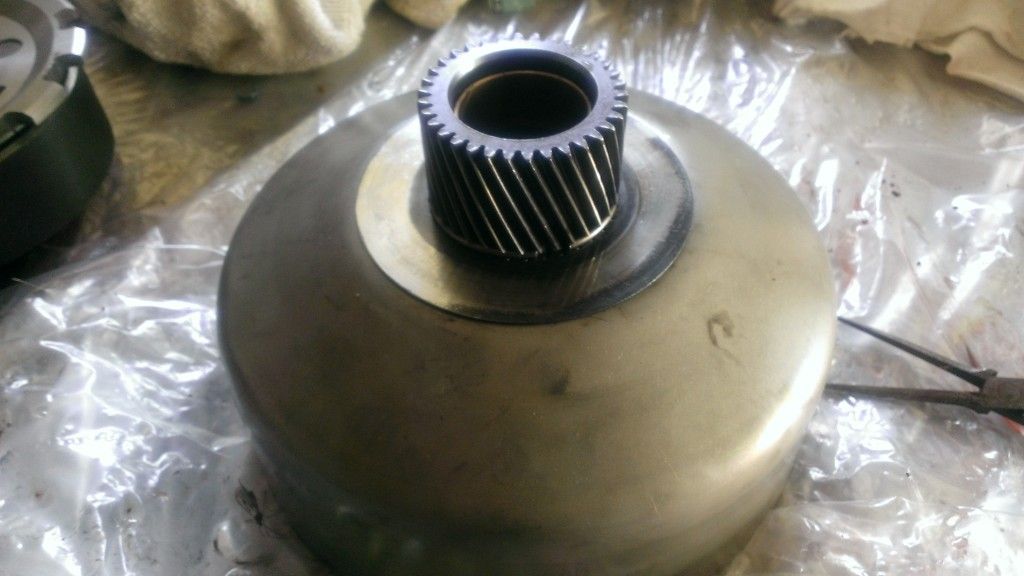
This is the main parts for the forward clutch, after cleaning and ready for assembly.
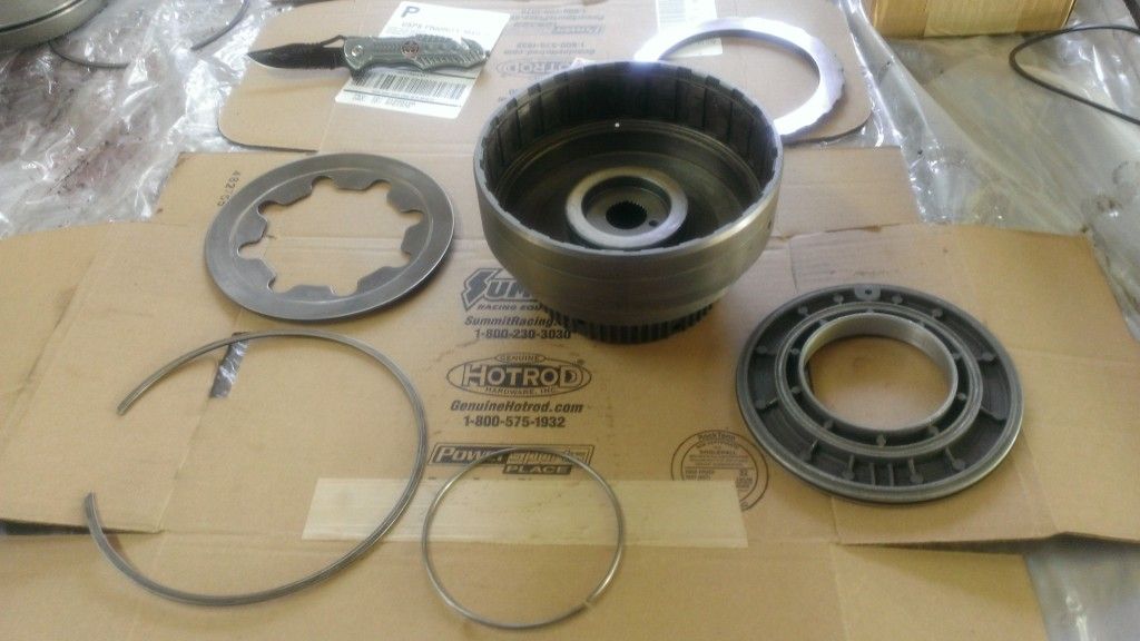
Post 1978 the seals here had a lip of the outer part of the plunger. Before that they are square cut, The real difference you need to know is that the style with the lip has a correct orientation, and great care is needed during installation not to damage the lip. In my case I have square cut so I will be showing that to you.
I use Vaseline as my choice of assembly lube because it works well and it will hold thrust washers in place. Once it is hot it will melt away and not degrade the transmission fluid.
There is a ball check in the plunger you need to make sure is loose and rattles around inside as well. Next I pushed the plunger into place. Be gentle but firm. If you have the lip type seal, you will need a special ring that will protect the seal during this step.
This is the main parts for the forward clutch, after cleaning and ready for assembly.
Post 1978 the seals here had a lip of the outer part of the plunger. Before that they are square cut, The real difference you need to know is that the style with the lip has a correct orientation, and great care is needed during installation not to damage the lip. In my case I have square cut so I will be showing that to you.
I use Vaseline as my choice of assembly lube because it works well and it will hold thrust washers in place. Once it is hot it will melt away and not degrade the transmission fluid.
There is a ball check in the plunger you need to make sure is loose and rattles around inside as well. Next I pushed the plunger into place. Be gentle but firm. If you have the lip type seal, you will need a special ring that will protect the seal during this step.
#27
05-08-2014, 01:52 AM
Next is the steel ring that the Belleville Spring rides on.
Next is the Belleville spring and snap ring. The Snap ring is going to have to be worked into position, and I just started at one end and worked my way around. Make sure that the "fingers" of the spring are going down during installation, otherwise your transmission will fail to work correctly once you have it back on the road......
Next is the Belleville spring and snap ring. The Snap ring is going to have to be worked into position, and I just started at one end and worked my way around. Make sure that the "fingers" of the spring are going down during installation, otherwise your transmission will fail to work correctly once you have it back on the road......
#28
05-08-2014, 02:17 AM
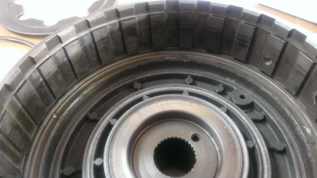
Next is the forward bottom pressure plate. This is the only one in the transmission that is half rounded on one side and flat on the other. Install with the rounded side down.
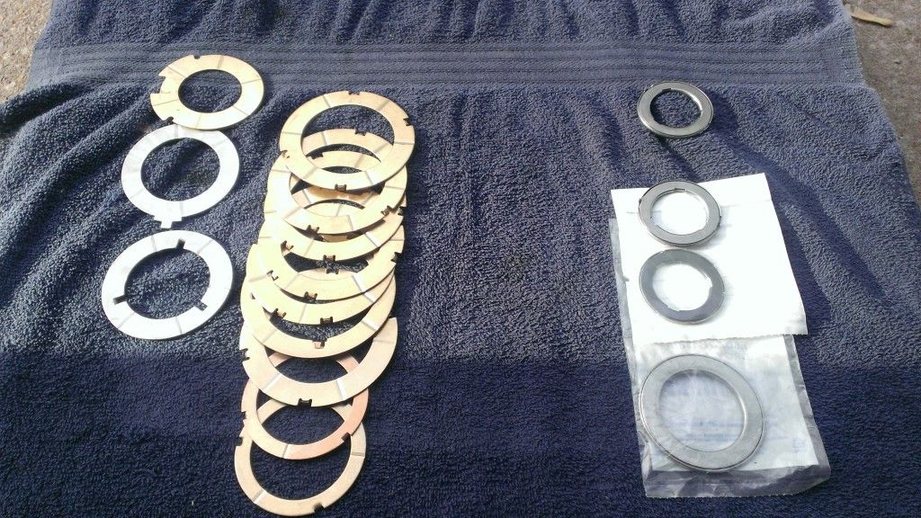
Next are the clutches. It is important to point out that the newer model C6s had a wavy spring that would be installed at this point during a typical build. Older models do not, and in fact mine was not equipped with one. If you want to install 5 clutches you can disregard the wave spring and this will give you the room for the additional clutch. You need to soak your friction plates at least 20 min before installing, I typically will soak them over night. You start with the friction plate, then you lay a steel plate. you will finish with a friction plate then lay the top pressure plate.
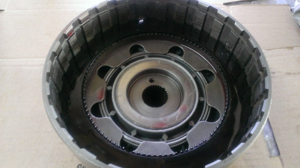
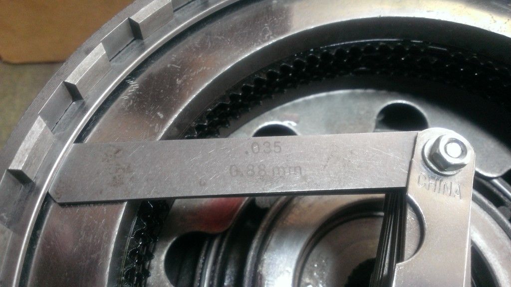
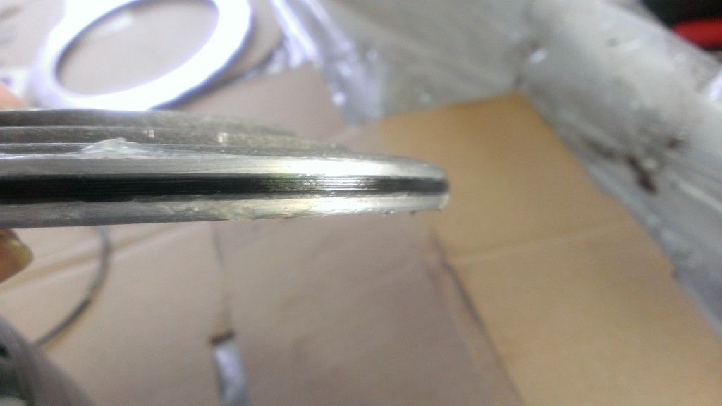
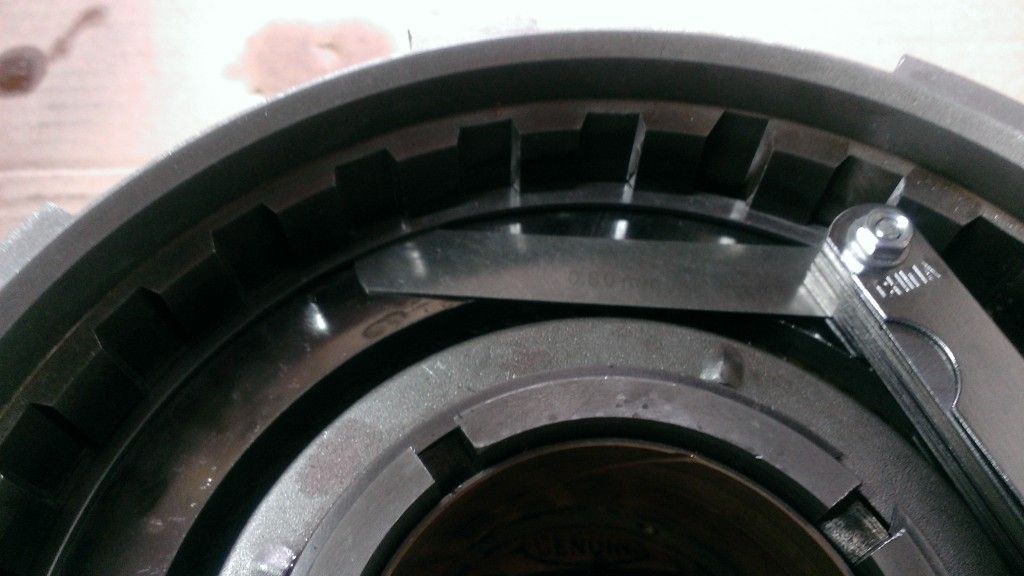
Once you have the pressure plate installed you can check the gap between the pressure plate and snap ring. .030 - .050. I am at .040 (there is a .005 gauge under the .035 that you can see) here. you can get snap rings with different thicknesses to change that gap so make sure you are with in the tolerance. I like to run kinda middle of the road to give room for expansion when hot.
Next are the clutches. It is important to point out that the newer model C6s had a wavy spring that would be installed at this point during a typical build. Older models do not, and in fact mine was not equipped with one. If you want to install 5 clutches you can disregard the wave spring and this will give you the room for the additional clutch. You need to soak your friction plates at least 20 min before installing, I typically will soak them over night. You start with the friction plate, then you lay a steel plate. you will finish with a friction plate then lay the top pressure plate.
Once you have the pressure plate installed you can check the gap between the pressure plate and snap ring. .030 - .050. I am at .040 (there is a .005 gauge under the .035 that you can see) here. you can get snap rings with different thicknesses to change that gap so make sure you are with in the tolerance. I like to run kinda middle of the road to give room for expansion when hot.
#30
05-08-2014, 02:45 AM
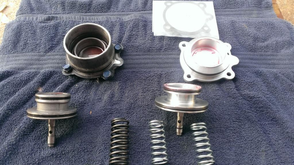
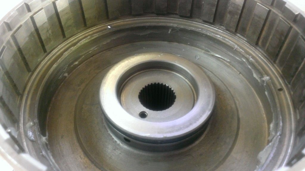
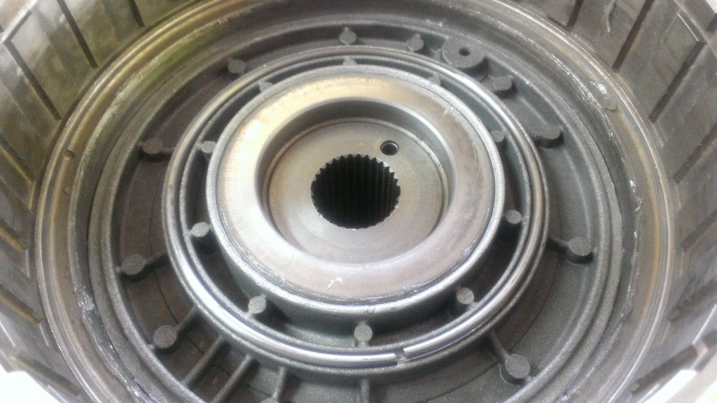
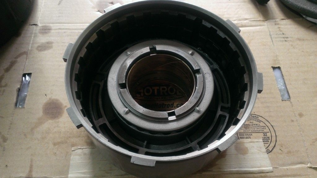
Here are the parts for this next assembly
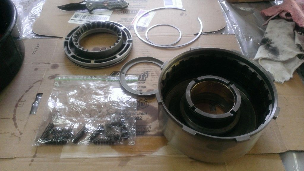
and just like before there are square cut seals on the outside edge of the plunger and the inner hub of the drum. I have also dressed the drum using 400 grit sand paper.
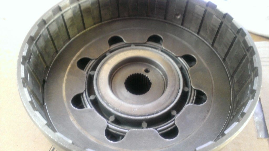
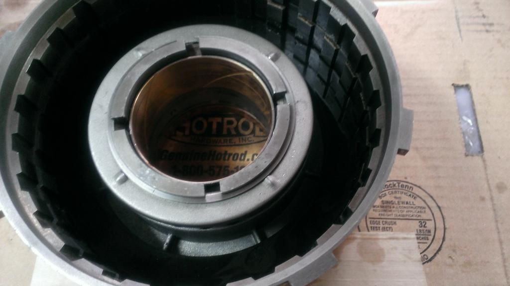
After you have installed the plunger you will take your springs and insert them into the plunger. Note the location of the springs in this picture. Unless you had springs in every spot, this is how they need to be spaced.
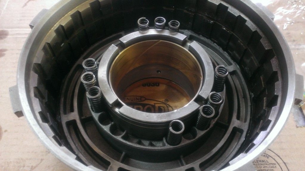
Followed by the spring cap and snap ring.
OK, I am going to say, there is a special tool for this that compresses the springs so that you can install the snap ring for the cap. I don't have the tool, but trust me when I say it is near impossible to do with out one.
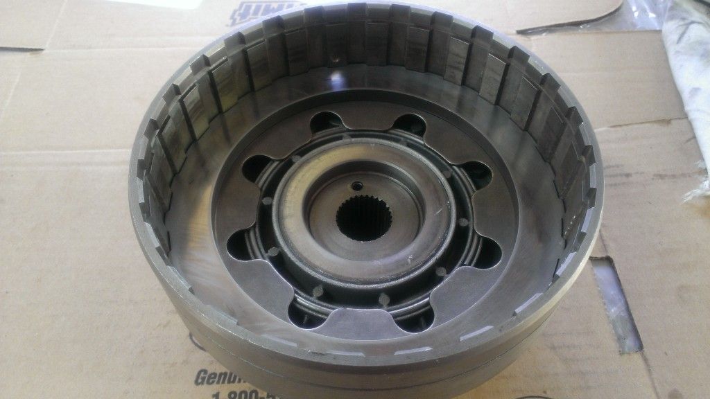
Next are the clutches and they go in like before only you will start with a steel, not a pressure plate then friction plate, you will still end with a friction plate followed by pressure plate.mine held 3 clutches.
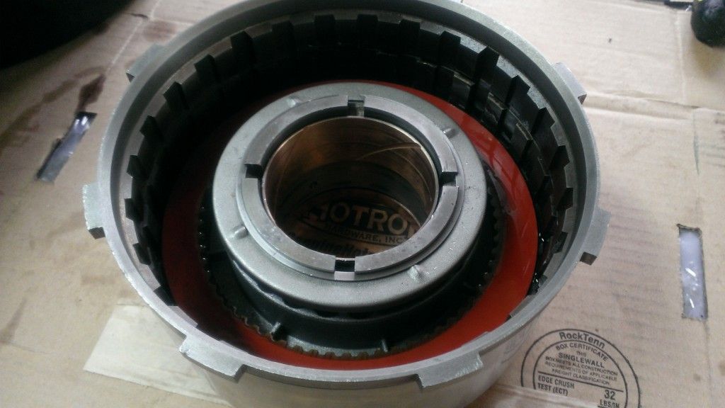
Specs here are between .020 and .040 and I was at .032.
and just like before there are square cut seals on the outside edge of the plunger and the inner hub of the drum. I have also dressed the drum using 400 grit sand paper.
After you have installed the plunger you will take your springs and insert them into the plunger. Note the location of the springs in this picture. Unless you had springs in every spot, this is how they need to be spaced.
Followed by the spring cap and snap ring.
OK, I am going to say, there is a special tool for this that compresses the springs so that you can install the snap ring for the cap. I don't have the tool, but trust me when I say it is near impossible to do with out one.
Next are the clutches and they go in like before only you will start with a steel, not a pressure plate then friction plate, you will still end with a friction plate followed by pressure plate.mine held 3 clutches.
Specs here are between .020 and .040 and I was at .032.