
Electric fuel pump conversion (pics)
#1
 04-20-2014, 03:15 PM


Electric fuel pump conversion (pics)
<<< PLEASE DO NOT QUOTE THIS ENTIRE POST WHEN REPLYING >>>
I'm sharing my latest project since this topic comes up fairly often and people are always looking for ideas. This is on a '79 2WD with a single 19-gallon aft tank. The truck has a straight six with some existing modifications (4-barrel intake and carb, for starters), so it's non-factory to begin with (in particular, the 90-degree orientation of the carburetor requires some creativity in terms of fuel line routing and throttle linkage).
This wasn't a project I had planned on doing. I started out with the simple goal of replacing the original mechanical fuel pump, which proved to be a disaster. All told, I could not find a single replacement pump that actually functioned properly. I tried at least 4 brands if memory serves me correctly. Some pumps had the incorrect inlet fitting size; others were made so cheaply that they would leak or practically fall apart. I found that most were made out of pot metal so soft that simply torquing down the bolts would grind into the pump body, preventing it from seating completely. Worse than that, the flare surface of the integral outlet fitting was so cheaply made that even the most gentle seating of a flared line would indent the cone. I never found a pump that fit and did not leak.
Oddly enough, after having bounced that complaint off some folks in the straight six forum, I found I was not alone. The advice I was given was that if you keep searching and replacing, you'll eventually get a pump that works. However, I was out of patience, and ultimately decided to do an electric pump conversion - this way all the fittings and connections are made with common, replaceable parts from the hardware store. There must just be something about replacement pumps for these engines. I don't know what it is, and I got tired of caring.
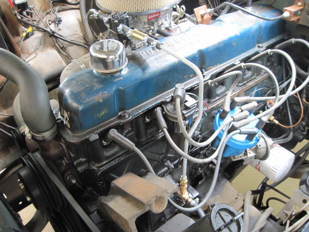
To begin, here's a shot of the engine. As I said before, I've already got a modified setup. You can see where the fuel pump used to be on the driver side of the block, is now fixed with a block-off plate and a homemade adapter. I've got a newly-made line wrapping up and around the engine over to the carburetor.
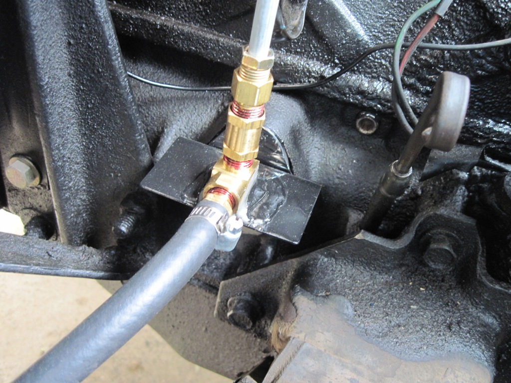
Here's a closeup of that adapter plate. I put this together so that I could keep the original line from the tank running up to where it was, but still use a hard line up and over the engine. The inlet and outlet connections are the same size as what would have appeared on the stock pump. Don't worry, the sealer is specially made for gasoline applications and is applied in such a way so that the excess backs out of the joint.
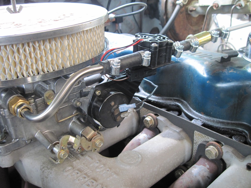
Here's the other end of the line, at the carburetor. The black device with the arrow is NOT a regulator, as one might think. It's actually a fuel flow rate sensor for an upcoming (and unrelated) project. The fuel pump I used (described farther down) is internally regulated with no need for a separate regulator. The sensor sits on a homemade choke cap bracket. The line between this device and the carburetor inlet is another custom piece.
Some details on the wiring before I move out of the engine bay: here's my hot-at-all times junction off the solenoid (also servicing an electric fan). This is just the main power feed to the pump; the control of the pump is handled by switched power (more on that farther down). You can see the power feed running off along the fender to a fuse carriage before disappearing in conduit.
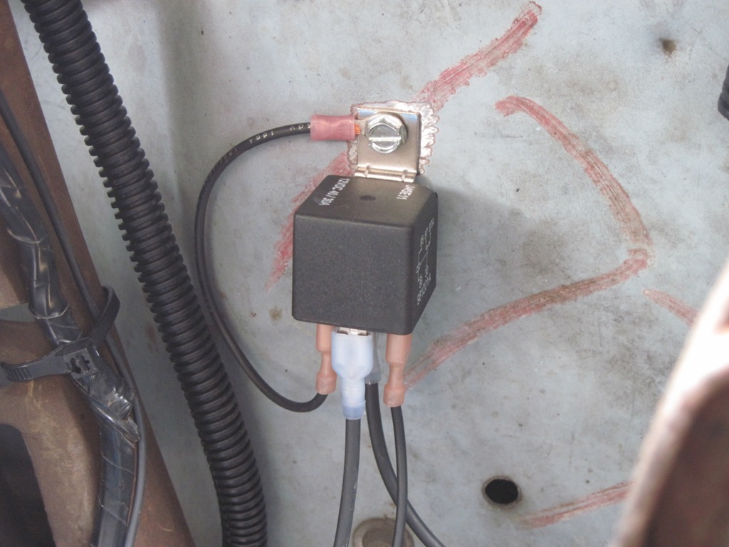
Here's the fuel pump relay fixed to the firewall. Not much to see here. It switches the heavy-duty power feed to the pump based on its trigger signal (described next).
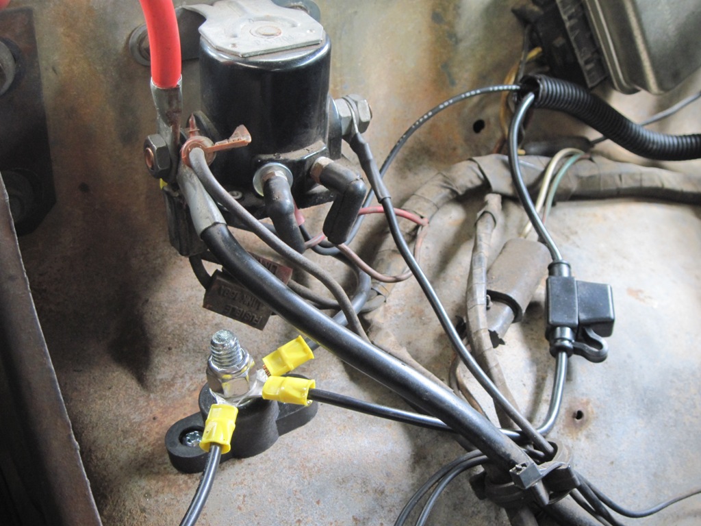
Here's the "Hobbs switch" that tells the pump when to turn on, based on oil pressure. When the key is in START (engine cranking), the pump is turned on. When the key is in RUN, the pump is turned on only when there is enough oil pressure. This is a safety feature to cut power to the pump if the engine stops. This device is a must for this type of conversion.
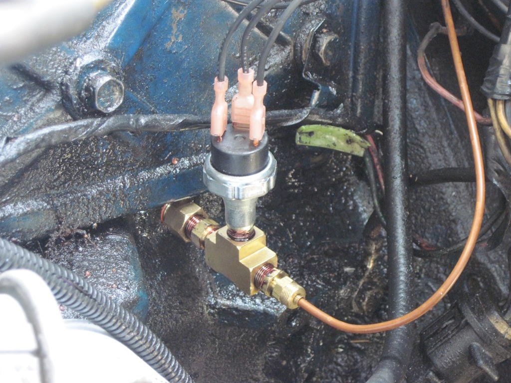
Please excuse the filthy engine. These engines are notorious for having leaky lifter covers. The goo on the threads is excess sealer, not oil.
The switch is tee'd off of the same location as the line that runs to my oil pressure gauge in the cab. There's actually another oil galley tap in the block, but I wasn't able to work the pipe plug loose. For fear of rounding off the factory plug, I just re-used the original sending unit location.
And finally, a shot of the pump (Carter P4070). I used this pump instead of the more popular Holley "Red" pump because this particular Carter pump awards some more freedom in actual pump location relative to the tank. The Holley pump is actually pretty strict about where it goes relative to the tank and if you look at a lot of people's conversions, they've actually got the pump in a bad spot and are just getting lucky.
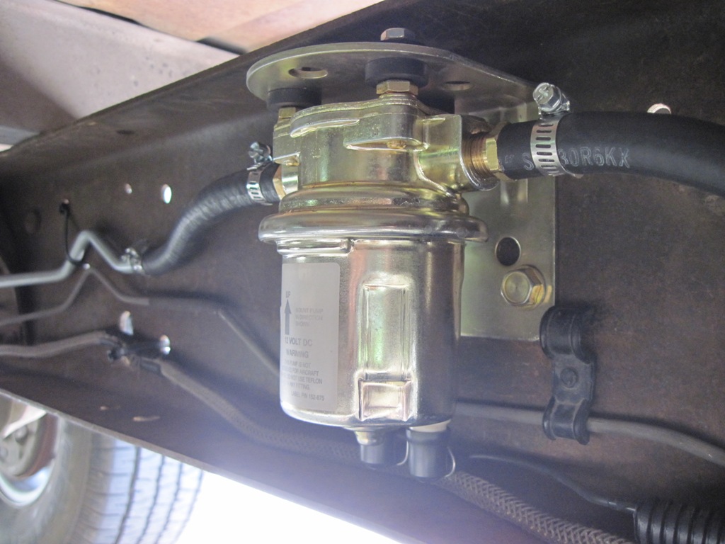
I installed the pump near the factory break in the fuel line to minimize fuel line re-work. I was able to keep the forward fuel line untouched, and simply had to knock the rear line back (for all lines, I mocked up what I wanted, then sent to Inline Tube for custom duplication and flaring/beading).
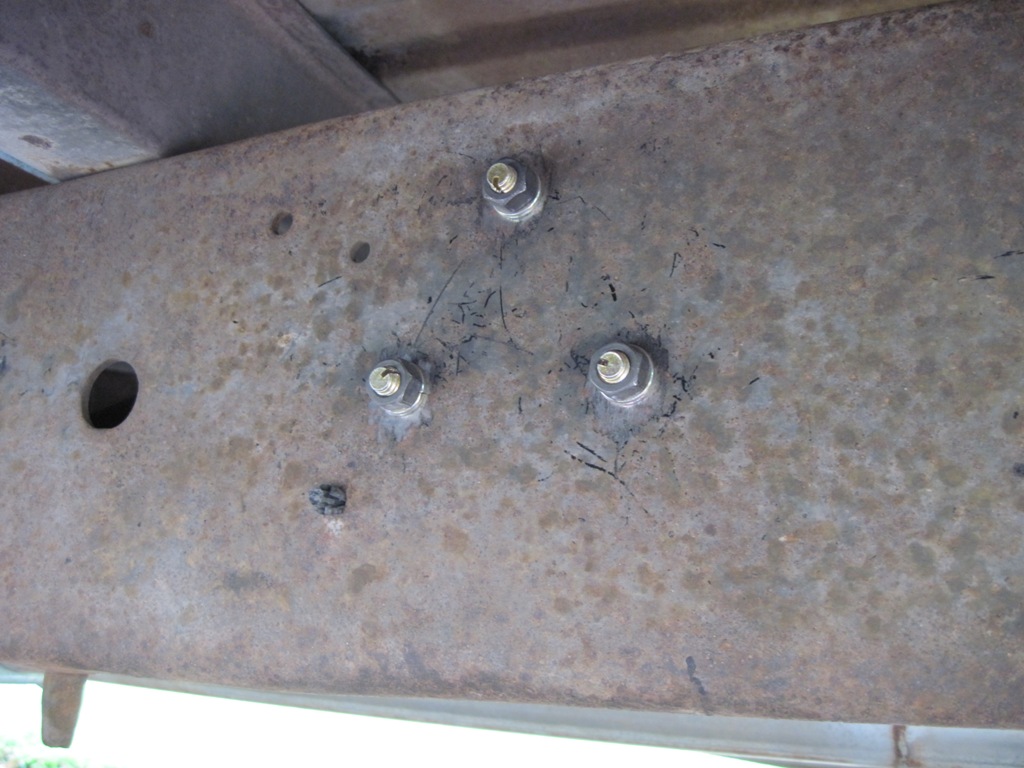
For kicks, here are the bolts on the other side of the frame. The pump grounds through the frame itself, so care was taken to minimize impedance between the pump and the engine block.
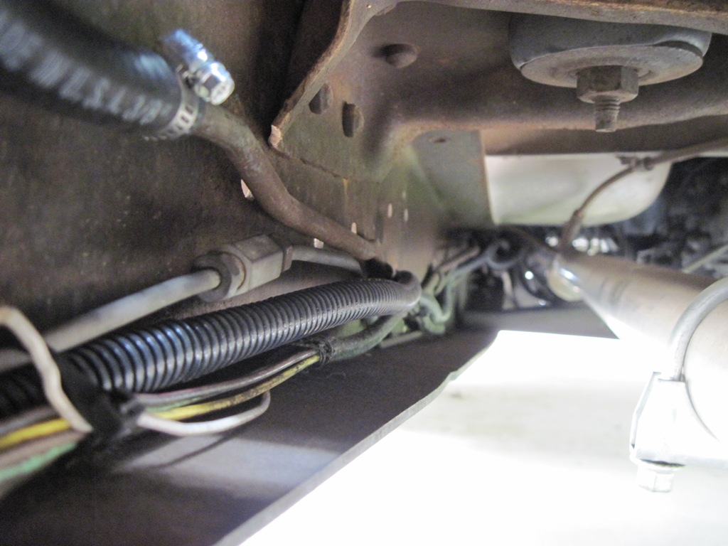
A quick shot of the pump wiring running up the frame (protected by conduit, tucked away from heat and the shifter linkage):
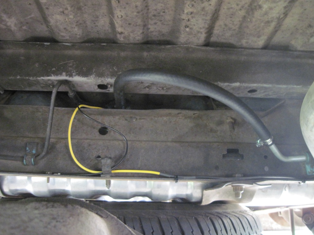
Here's a quick shot of the rear line terminating at the tank. Nothing was really changed here, but you can tell the line is new. I did replace the tank and sending unit, as well as R/R'd the wiring, but that was all before the conversion. It's nice to have a fuel gauge again.
That's all I've got. Would I have done this if I didn't have to? Probably not, but I will say that I'm very pleased with how fast the new pump gets fuel to the carburetor when priming for the first time. The pump isn't too loud, although you can tell it's there to some degree when idling in an enclosed place (drive-thru, etc).
Another option here is to install an inertia switch to kill the pump right away in the event of a collision where the engine does NOT shut off. This would be a second switch on top of the existing pressure cut-off switch. I didn't install an inertia switch up front because they're actually rather expensive, and I wanted to see how the conversion turned out first. However, with an oil pressure cut-off switch, an electric pump is at least as safe as a mechanical pump. I will note, however, that if the engine stalls for an unrelated reason and you leave the key on, the pump doesn't shut off that very second - it does take a moment for the oil pressure to fall enough to cut the switch. It's something to keep in mind if you're out there working (dialing in the carburetor, etc) where the engine might stall out and you're not necessarily paying attention to the key.
Anyway, hopefully that was interesting and comes in useful for someone thinking about doing the conversion.
I'm sharing my latest project since this topic comes up fairly often and people are always looking for ideas. This is on a '79 2WD with a single 19-gallon aft tank. The truck has a straight six with some existing modifications (4-barrel intake and carb, for starters), so it's non-factory to begin with (in particular, the 90-degree orientation of the carburetor requires some creativity in terms of fuel line routing and throttle linkage).
This wasn't a project I had planned on doing. I started out with the simple goal of replacing the original mechanical fuel pump, which proved to be a disaster. All told, I could not find a single replacement pump that actually functioned properly. I tried at least 4 brands if memory serves me correctly. Some pumps had the incorrect inlet fitting size; others were made so cheaply that they would leak or practically fall apart. I found that most were made out of pot metal so soft that simply torquing down the bolts would grind into the pump body, preventing it from seating completely. Worse than that, the flare surface of the integral outlet fitting was so cheaply made that even the most gentle seating of a flared line would indent the cone. I never found a pump that fit and did not leak.
Oddly enough, after having bounced that complaint off some folks in the straight six forum, I found I was not alone. The advice I was given was that if you keep searching and replacing, you'll eventually get a pump that works. However, I was out of patience, and ultimately decided to do an electric pump conversion - this way all the fittings and connections are made with common, replaceable parts from the hardware store. There must just be something about replacement pumps for these engines. I don't know what it is, and I got tired of caring.
To begin, here's a shot of the engine. As I said before, I've already got a modified setup. You can see where the fuel pump used to be on the driver side of the block, is now fixed with a block-off plate and a homemade adapter. I've got a newly-made line wrapping up and around the engine over to the carburetor.
Here's a closeup of that adapter plate. I put this together so that I could keep the original line from the tank running up to where it was, but still use a hard line up and over the engine. The inlet and outlet connections are the same size as what would have appeared on the stock pump. Don't worry, the sealer is specially made for gasoline applications and is applied in such a way so that the excess backs out of the joint.
Here's the other end of the line, at the carburetor. The black device with the arrow is NOT a regulator, as one might think. It's actually a fuel flow rate sensor for an upcoming (and unrelated) project. The fuel pump I used (described farther down) is internally regulated with no need for a separate regulator. The sensor sits on a homemade choke cap bracket. The line between this device and the carburetor inlet is another custom piece.
Some details on the wiring before I move out of the engine bay: here's my hot-at-all times junction off the solenoid (also servicing an electric fan). This is just the main power feed to the pump; the control of the pump is handled by switched power (more on that farther down). You can see the power feed running off along the fender to a fuse carriage before disappearing in conduit.
Here's the fuel pump relay fixed to the firewall. Not much to see here. It switches the heavy-duty power feed to the pump based on its trigger signal (described next).
Here's the "Hobbs switch" that tells the pump when to turn on, based on oil pressure. When the key is in START (engine cranking), the pump is turned on. When the key is in RUN, the pump is turned on only when there is enough oil pressure. This is a safety feature to cut power to the pump if the engine stops. This device is a must for this type of conversion.
Please excuse the filthy engine. These engines are notorious for having leaky lifter covers. The goo on the threads is excess sealer, not oil.
The switch is tee'd off of the same location as the line that runs to my oil pressure gauge in the cab. There's actually another oil galley tap in the block, but I wasn't able to work the pipe plug loose. For fear of rounding off the factory plug, I just re-used the original sending unit location.
And finally, a shot of the pump (Carter P4070). I used this pump instead of the more popular Holley "Red" pump because this particular Carter pump awards some more freedom in actual pump location relative to the tank. The Holley pump is actually pretty strict about where it goes relative to the tank and if you look at a lot of people's conversions, they've actually got the pump in a bad spot and are just getting lucky.
I installed the pump near the factory break in the fuel line to minimize fuel line re-work. I was able to keep the forward fuel line untouched, and simply had to knock the rear line back (for all lines, I mocked up what I wanted, then sent to Inline Tube for custom duplication and flaring/beading).
For kicks, here are the bolts on the other side of the frame. The pump grounds through the frame itself, so care was taken to minimize impedance between the pump and the engine block.
A quick shot of the pump wiring running up the frame (protected by conduit, tucked away from heat and the shifter linkage):
Here's a quick shot of the rear line terminating at the tank. Nothing was really changed here, but you can tell the line is new. I did replace the tank and sending unit, as well as R/R'd the wiring, but that was all before the conversion. It's nice to have a fuel gauge again.
That's all I've got. Would I have done this if I didn't have to? Probably not, but I will say that I'm very pleased with how fast the new pump gets fuel to the carburetor when priming for the first time. The pump isn't too loud, although you can tell it's there to some degree when idling in an enclosed place (drive-thru, etc).
Another option here is to install an inertia switch to kill the pump right away in the event of a collision where the engine does NOT shut off. This would be a second switch on top of the existing pressure cut-off switch. I didn't install an inertia switch up front because they're actually rather expensive, and I wanted to see how the conversion turned out first. However, with an oil pressure cut-off switch, an electric pump is at least as safe as a mechanical pump. I will note, however, that if the engine stalls for an unrelated reason and you leave the key on, the pump doesn't shut off that very second - it does take a moment for the oil pressure to fall enough to cut the switch. It's something to keep in mind if you're out there working (dialing in the carburetor, etc) where the engine might stall out and you're not necessarily paying attention to the key.
Anyway, hopefully that was interesting and comes in useful for someone thinking about doing the conversion.
The following users liked this post:
#2
04-20-2014, 04:22 PM
you may want to reconsider that switch. My float got stuck, truck died and pump proceeded to fill 3 cylinders with fuel along with dumping a gallon or two on the ground before I caught it (truck was "warming up"). I won't put an electric pump in the one I'm building thanks to that headache.
#3
04-20-2014, 05:35 PM
you may want to reconsider that switch. My float got stuck, truck died and pump proceeded to fill 3 cylinders with fuel along with dumping a gallon or two on the ground before I caught it (truck was "warming up"). I won't put an electric pump in the one I'm building thanks to that headache.
The switch that I DID forgo is an inertia switch. This is a second line of defense in the event that the vehicle is in a collision and the engine does NOT shut off. That is a separate idea altogether that is less common. Running without that switch is no different than a mechanical setup.
The following users liked this post:
#7
04-21-2014, 01:04 AM
Trending Topics
#8
04-21-2014, 01:08 AM
Elder User
Join Date: Jun 2012
Location: Florida
Posts: 850
Likes: 0
Received 0 Likes
on
0 Posts

#9
04-21-2014, 07:46 AM
Thanks guys.
The Hobbs switch is Carter part number A68301: http://www.summitracing.com/parts/crt-a68301/overview/
The sealant is Permatex High-Tack; it's advertised as a gasket maker but also doubles as a thread sealer: Gasket Sealants : Permatex� High Tack
The Hobbs switch is Carter part number A68301: http://www.summitracing.com/parts/crt-a68301/overview/
The sealant is Permatex High-Tack; it's advertised as a gasket maker but also doubles as a thread sealer: Gasket Sealants : Permatex� High Tack
#10
04-21-2014, 08:35 AM
 .
.
#11
04-21-2014, 02:43 PM

 .
.
#13
04-21-2014, 05:18 PM
Thanks for the kind words guys.
That combined with the "Tornado" in my air cleaner. Assuming they still make those. And all the magnets along the fuel lines 
The credit does to Inline Tube for that one. The mockups I sent them were pretty unprofessional looking, with the exception of the rear fuel line where I simply cut back the original and asked that they add a bead to the end of the duplicate.
The credit does to Inline Tube for that one. The mockups I sent them were pretty unprofessional looking, with the exception of the rear fuel line where I simply cut back the original and asked that they add a bead to the end of the duplicate.
#14
04-22-2014, 08:25 AM

#15
04-22-2014, 09:16 PM
Posting Guru
Join Date: Jan 2001
Location: S. Mississippi
Posts: 2,357
Likes: 0
Received 0 Likes
on
0 Posts

