
Swap- 92 f150 to 95 Lighting speedometer.
#1
 02-25-2014, 07:46 PM

Hey Folks,
I been tired of my Tach not working and Speedometer needle bouncing all around for the past few years...Replaced diff sensor, the wiring and checked the diff...Still no fix there. So I decided to swap out my 1992 Speedometer cluster with a 1995 Lightning speedometer cluster I ordered...Has not arrived yet and hopefully they did not screw the order up....
Any way I still got to find some wiring diagrams on which wires need to be swapped. Curious to know if any one has done this swap before. Ill keep surfing the forums and the web to see if I can locate more information. Any information or links would be appreciated.
 [/IMG]
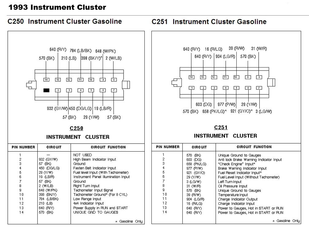

#4
02-26-2014, 09:58 PM
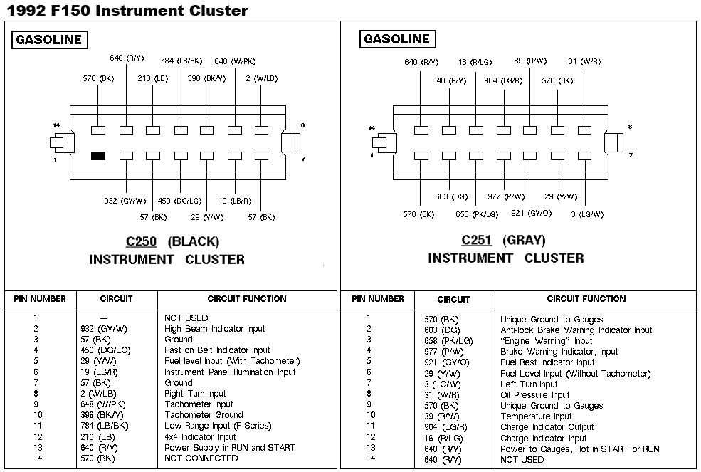
This is the plan on how I'm going to swap the wires.
From the original 1992 Cluster wiring I plan on cutting/soldering or removing and relocating these pins. I have never done this swap before...So if this information is wrong and needs to be adjusted please post.
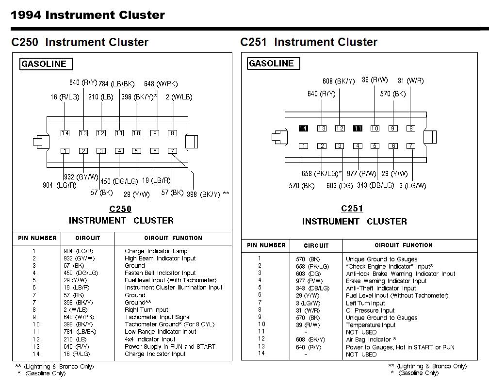
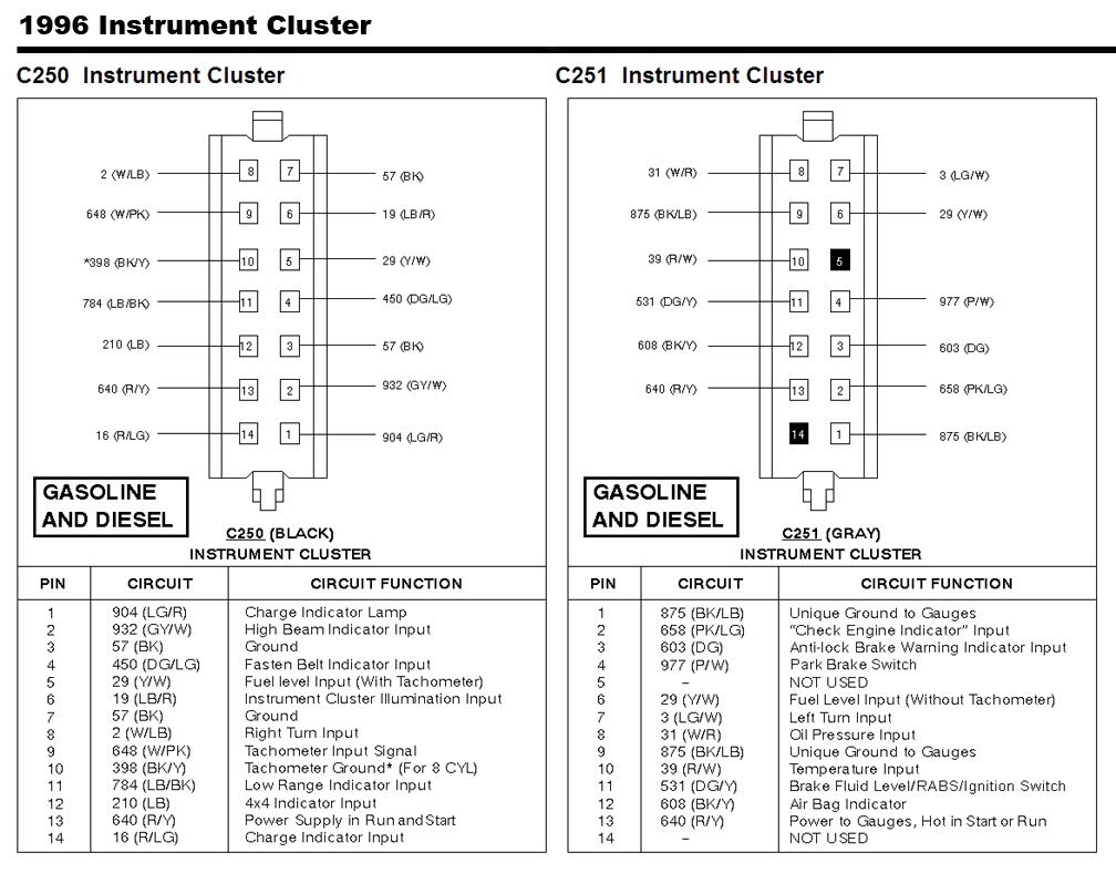
C250 "Black" Connector" Pin 1 needs to be swapped over to C251 "Grey" Connector Pin 11.
C251 "Grey" Connector Pin 2 and 3 in the grey connector need to be swapped.
C251 "Grey" Connector Pin 12 needs to go to C250 "Black Connector Pin 14
I do not have a air bag in my vehicle so I will leave C251 Pin 12 unplugged on the 95 Lightning cluster. If this causes a problem I will go from there.
The only problem I see is on C251 Pin 5....On the 95 Lightning Harness it is a anti-theft indicator input and on the 1992 wiring harness it is a Fuel Reset Indicator input...I will leave this alone and if some how the truck don't start and is not getting fuel and the fuel reset button needs to be pushed it will say "Theft" That's what I'm guessing...Kind of funny is that I have had this truck since 1992 and never even looked at or looked for the re-set switch. Only heard about it.
Any other suggestions?
From the original 1992 Cluster wiring I plan on cutting/soldering or removing and relocating these pins. I have never done this swap before...So if this information is wrong and needs to be adjusted please post.
C250 "Black" Connector" Pin 1 needs to be swapped over to C251 "Grey" Connector Pin 11.
C251 "Grey" Connector Pin 2 and 3 in the grey connector need to be swapped.
If you don't and if your check engine light comes on it will actually be your ABS warning indicator light.
C251 "Grey" Connector Pin 12 needs to go to C250 "Black Connector Pin 14
I do not have a air bag in my vehicle so I will leave C251 Pin 12 unplugged on the 95 Lightning cluster. If this causes a problem I will go from there.
Any other suggestions?
#5
03-05-2014, 12:37 AM
Your fuel reset will still say fuel reset if you use your old bezel. Plus, you'll still have the charge indicator instead of the airbag light, although I'd use the charge indicator in the cluster itself, looks cleaner I think and I believe it'll have to be that way for the charge circuit to work properly. And yes, this definitely can be done. I've heard the Lightning PSOM may cause a little trouble in a regular truck but I'm sure you can make it work. May take a little tweaking.
#6
03-12-2014, 09:17 AM
The swap was a success.
I had to add some extra length to two of the wires because they did not reach the other connector. I then just repined the wires in their connectors. Was really easy... Only needed to cut 2 wires. Every thing works great...Had a few burned out bulbs but that was an easy fix. Now instead of 279k miles I have 115k miles... The old girl lost some years.
I had to add some extra length to two of the wires because they did not reach the other connector. I then just repined the wires in their connectors. Was really easy... Only needed to cut 2 wires. Every thing works great...Had a few burned out bulbs but that was an easy fix. Now instead of 279k miles I have 115k miles... The old girl lost some years.
#7
03-12-2014, 09:49 AM
Senior User
Join Date: Jul 2011
Location: O'fallon, Missouri
Posts: 177
Likes: 0
Received 0 Likes
on
0 Posts
Trending Topics

#11
03-13-2014, 05:37 PM
Fleet Owner

#13
03-19-2014, 04:30 AM
Fleet Owner
#15
03-19-2014, 08:31 AM
I think the PSOM is the same.
I think the speedometer heads unifilar stepping motor has different windings to move the needle differently up the scale.
OR
The 3 plastic gears that operate a reduction on the output shaft for the needle may a have different number of teeth and of course the size of the gears would be different.
The OP needs to check the microprocessor revision level and see if it is revision level 08 like all of the microprocessor revision levels I have seen from 1992-1995.
To check the revision level of the microprocessor just:
1. Press and hold the RESET button on the front of the speedometer while turning the key to RUN. Do not start the engine just turn it to the RUN position.
2. Release the RESET button. The pointer will prove out and some codes will appear on the odometer display. If an "E" is on the left side of the display, the module is programmed for English display mode and should have English graphics (mph). A lower case "o" signifies an overseas (metric) graphics (kph).
3. The number appearing after the type is the microprocessor revision level.
4. Turn off the key to exit this verification.