Ranger 4.0L SOHC Supercharger Kit Install - How To
#1
 01-29-2014, 12:36 AM

Ranger 4.0L SOHC Supercharger Kit Install - How To
Ok. So there are alot of great "how to" guides on here... but I haven't seen a complete and thorough "how to" supercharger install for the 4.0L SOHC engine (specifically for Ford Ranger/2dr Explorer/Sport Trac & B4000).
So... here it goes. If you obtain a Moddbox Installation kit and any Eaton M90 supercharger (89-95 either style inlet), follow the following instructions and you're good to go. No tune required. 100% bolt-on mod. You can get your installation kit here:
ModdBoxModdBox - Engineering your driving experience @
I've also decided to post the "final result" first. If you like it.. proceed to read the "how to".
Here's a road test of the 3.5 psi pulley equipped with no cooling equipment installed.
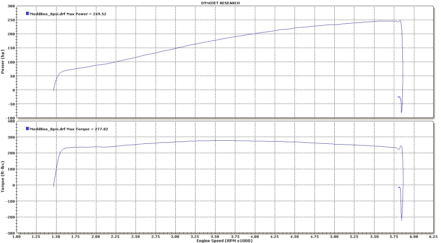
Here's the Dyno. 215 hp & 237 lbft at the rear wheels.
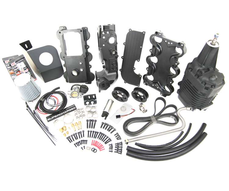
Kit Photo:
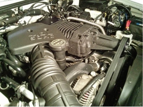
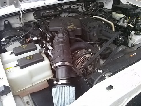
Installed Photos:
TOOLS REQUIRED
Tools Required:
Standard metric socket set
Needle Nose Pliers
T-30 Torx Bit
Fluid Funnel
Flat Head Screw Driver
Punch
...will add more soon
STOCK REFERENCE DIAGRAMS
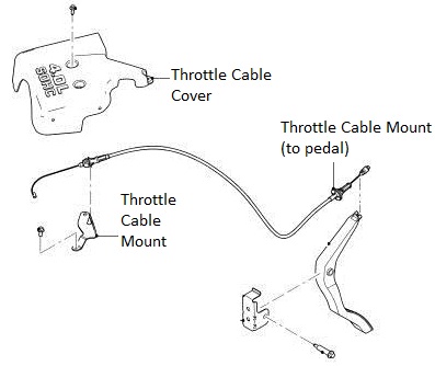
Stock Throttle Cable Reference Diagram
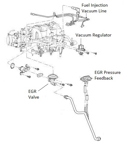
Stock EGR System Reference Diagram
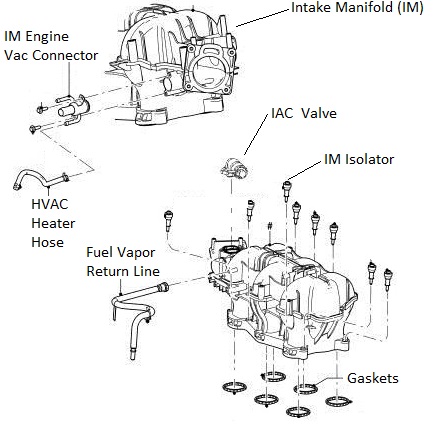
Stock Intake Manifold Reference Diagram
Stock Air Box Reference Diagram

Stock Throttle Reference Diagram

Belt Diagram Reference Diagram (Dark Belt Showing the ModdBox Orientation)

MODDBOX SUPERCHARGER KIT PARTS
ModdBox Supercharger Bypass Valve
http://modd.me/wp-content/uploads/2013/09/CAM04401.jpg
ModdBox 255lph Fuel Pump
http://modd.me/wp-content/uploads/20...dbox255lph.jpg
ModdBox Heat Shield
http://modd.me/wp-content/uploads/20...heatShield.jpg
ModdBox 70mm Air Filter
http://modd.me/wp-content/uploads/20...yAirFilter.jpg
ModdBox Throttle Cable and Cruise Control Mount
http://modd.me/wp-content/uploads/20...eInstall-7.jpg
ModdBox 3.0 & 3.5 psi Supercharger Pulleys
http://modd.me/wp-content/uploads/2013/11/CAM04371.jpg
ModdBox Supercharger Pulley Quick Adapter
http://modd.me/wp-content/uploads/20...apterPully.jpg
ModdBox Plenum Bottom Plate
http://modd.me/wp-content/uploads/20...eInstall-9.jpg
ModdBox Plenum Top Plate
http://modd.me/wp-content/uploads/20...Install-10.jpg
ModdBox Intake Manifold
http://modd.me/wp-content/uploads/20...Install-11.jpg
ModdBox Intake Manifold Top
http://modd.me/wp-content/uploads/20...Install-12.jpg
ModdBox M22-1.5mm EGR Extension
http://modd.me/wp-content/uploads/2013/11/CAM04413.jpg
Black Silicone Liquid Gasket
http://modd.me/wp-content/uploads/2013/11/CAM04389.jpg
6pk Serpentine Belt
http://modd.me/wp-content/uploads/2013/11/6pkBelt.jpg
1/4" Electrical Loom
16 ga wire & connections
Heater Hose
Fuel Hose
Hardware and Fittings
INSTALLATION STEPS
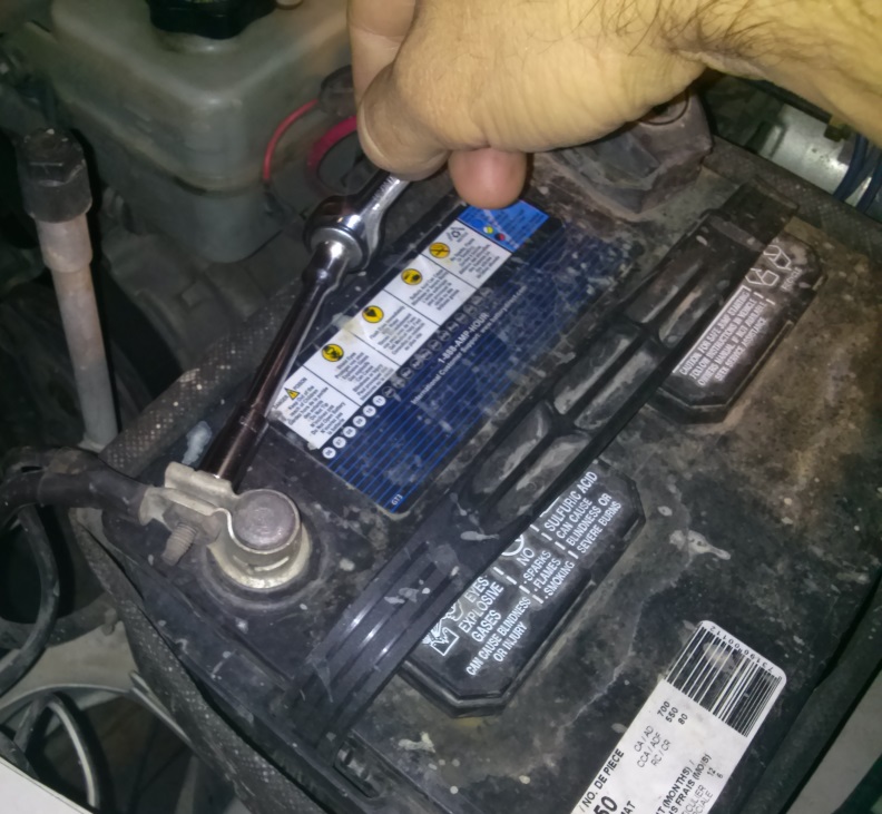
Remove the negative battery cable (1 bolt). Secure it to the side of the battery to prevent any accidental contact with the negative terminal.
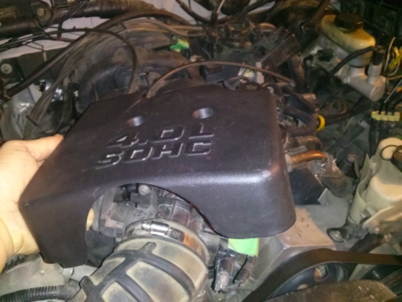
Remove the Throttle Body Cover (2 bolts). If your model is equipped with a second Crank Case Ventilation hose, you will be required to remove the hose clips on the side of the Throttle Body Cover (not shown here).
Loosen the hose clamp and disconnect the Intake Tube from the Stock Air Box Assembly.

Loosen the hose clamp and disconnect the Intake Tube from the Throttle Body.

Disconnect the Crank Case Vent Hose(s) and remove the Intake Tube. Set the Intake Tube aside for later use. Some models have a second Crank Case Vent Hose. For more information, see the Stock Setup Diagrams provided at the beginning of this instruction manual.
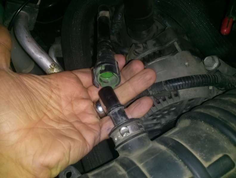
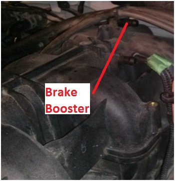
Remove the Brake Booster Line from the back of the Intake Manifold. Tape and label if necessary.
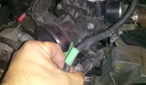
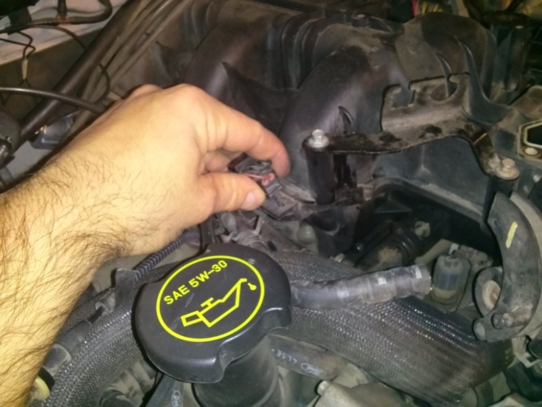
Unplug the cable connected to the IAC Valve.

Unbolt and remove the IAC Valve (2 bolts). Set the IAC Valve aside for later use.

Unplug the Vac line connected to the EGR. Tape and label the Vac Line if necessary.

Unbolt the EGR Valve (2 – 12mm bolts).

Remove EGR Valve by disconnecting the EGR Tube. Set the EGR Valve aside for later use.
Unplug the TPS Sensor. Tape and label the plug if necessary.
Remove the Throttle Cable from the Throttle Body Valve. The cable can be slipped free by manually actuating the valve 90 degrees and providing slack in the cable.

Unbolt the Throttle Body Valve (4 bolts). Set the Throttle Body Valve aside for later use.

Disconnect the Throttle Cable and the Cruise Control Cable.

Disconnect the electrical wire mount from the left side of the Intake Manifold.
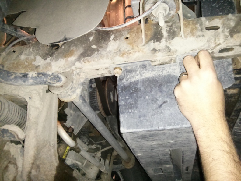
Locate the plastic Radiator Rock Shield located underneath the engine bay. Remove the bolts and set it aside.
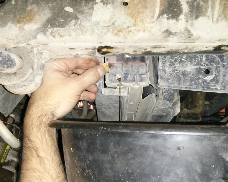
Locate the plastic Radiator Drain Valve at the bottom passenger side of the Radiator. Turn this plug and release only approximately a 3/4 gallon of coolant fluid (~3L). This is to allow the removal and relocation of coolant lines in the proceeding steps.
Remove the HVAC Heater Hoses (2x 1/4” diameter) and the Intake Manifold Engine Vac Line (5/8” diameter) from the Hose Connector Fitting. Tape and label the hoses if necessary.

Remove the Hose Connector Fitting. Set the Hose Connector Fitting aside for later use.

Locate the 1 5/8” diameter Radiator to Thermostat Coolant Hose.
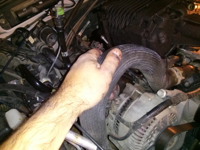
Relocate the Coolant Hose to be in front of the Oil Cap and around the AC Line as illustrated. Cut approximately 5” to 6” off of the hose and re-secure it to the radiator.
Be sure the hose will not conflict with the belt. If not equipped with AC, secure the hose with restraining straps if necessary. Do not dispose of the 1 5/8” hose. The remaining hose will be needed in a later step.

Remove the Fuel Injection Vac Line located on the right side of the Intake Manifold. Tape and label it if necessary.
Pry off the Ignition Wire Mount located at the top of the Intake Manifold.

Unbolt the Ignition Wire Flange Mount.

With the Ignition Wire Flange Mount disconnected from the Intake Manifold, proceed to pry the Ignition Wire Flange Mount approximately 2 inches toward the driver side. This additional clearance will aid in the removal of the stock Intake Manifold as well as providing ample space for the future EGR Valve.
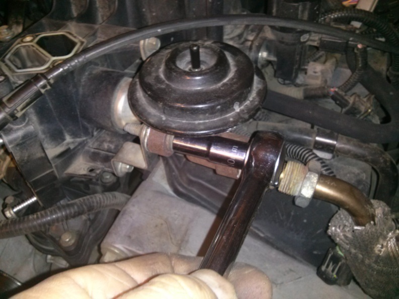
Unbolt the Vacuum Regulator (2 bolts) located towards the front drivers side of the Intake Manifold.

Remove the Fuel Vapor Return Line. This fitting is equipped with a simple push-style fitting. Simply push in the large curved shape and the fitting should pull off.
Remove the Throttle Cable and Cruise Control Cable Mount (2-bolts).

Loosen the Intake Manifold Bolts (12 – T30 Torx bolts). Note that these bolts do not remove completely. Once turned out of the Engine Block, the bolts remain connected to the Intake Manifold. Caution: You do not want to strip these bolts. It is advisable to inspect the Torx heads and use a vacuum to remove any dirt that may have accumulated inside the head. It may be necessary to use a machinist scribe or similar pointed object to loosen and vacuum out any dirt that may be residing inside the Torx heads before attempting to remove.
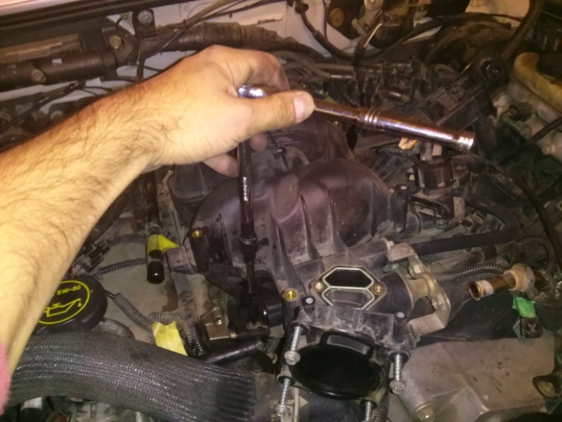
Lift out the Intake Manifold.

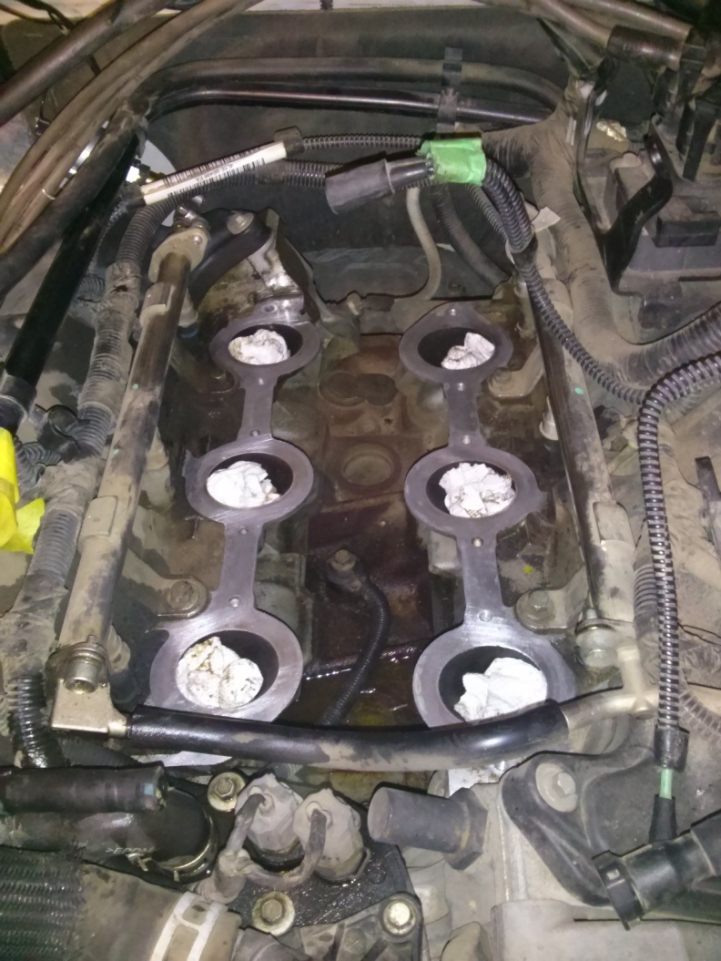
Caution: Do not drop anything into the Intake Ports. Before Proceeding, fill the Intake Ports with rags or paper towel. Clean and vacuum the area if necessary. Be sure to clean the Engine Block’s mating faces.
You are now ready to being modding your 4.0L J
Obtain the provided ModdBox stainless steel Supercharger Pulley Adaptor. Slip the supercharger Adapter onto your Eaton M90 Supercharger shaft until it binds (either an 89-93 oval or 94-95 rectangular style M90). The pulley is designed to have an interference fit which will cause the pulley to jam once it slips halfway onto the shaft. Use the stock Eaton M90 Supercharger lock nut to ratchet the pulley down the remaining length of the shaft until the Adapter hits the stop on the shaft. You may also want to use a press if you have one available. It is recommended that you use a low torque setting on an air or electric hammer-ratchet to suck the pulley down to the stop. If you do not have an automatic ratchet, you may carefully use a piece of soft lumber to stop the motion of the supercharger rotors. This will allow you to ratchet down the supercharger lock nut with a standard ratchet. Caution: Be sure that no debris falls into your Eaton M90 Supercharger. The tolerances on your supercharger are only a few thousandths of an inch and may be damaged if material falls or gets sucked into the supercharger housing. Even rotating the rotors by hand can often pull enough air to suck debris into the rotors. Use a vacuum to clear your rotors prior to installation.
<photo coming soon>
Obtain the provided ModdBox 6PK Custom Pulley and slip it onto the Supercharger Pulley Adaptor. Use the provided M5x16mm socket head cap screws.
<photo coming soon>
Locate the provided Black Liquid Gasket. Apply a thin bead of the gasket to the Eaton M90 Supercharger flange as illustrated.
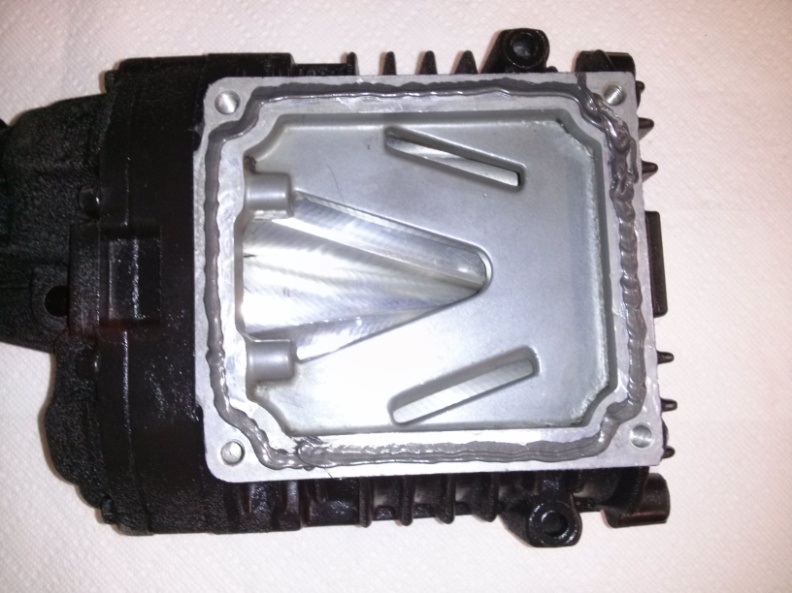
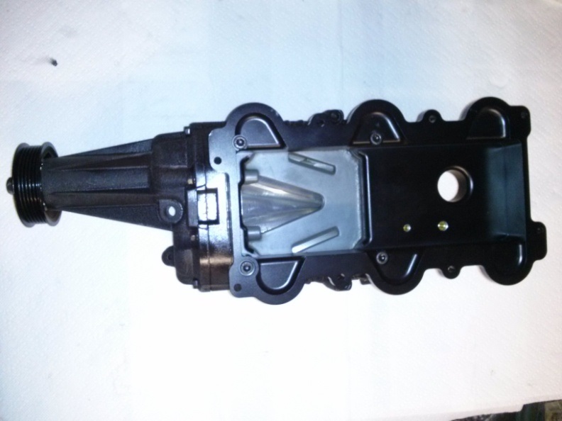
Obtain the ModdBox Plenum Top Plate and bolt it to the base of the Eaton M90 Supercharger & Pulley Assembly. Use the provided M8x40mm socket head cap screws. Clean any excess gasket material.
Use the extra 1 5/8” diameter Radiator Hose that was remaining from a previous step. Measure out and cut a length of hose as is required for your supercharger:
For the 94’-95’ Eaton M90 Supercharger (rectangular inlet): 1-7/8”
For the 89’-93’ Eaton M90 Supercharger (oval inlet): 2-5/8”
Use one of the 2” stainless hose clamps to secure the hose to the Plenum Top Plate. Loosely place the other 2” diameter stainless hose clamp on the hose. Place the entire assembly aside for later use.

Obtain the ModdBox Plenum Base Plate. Apply a small bead of the provided Black Liquid Gasket around each Intake Port hole as shown.
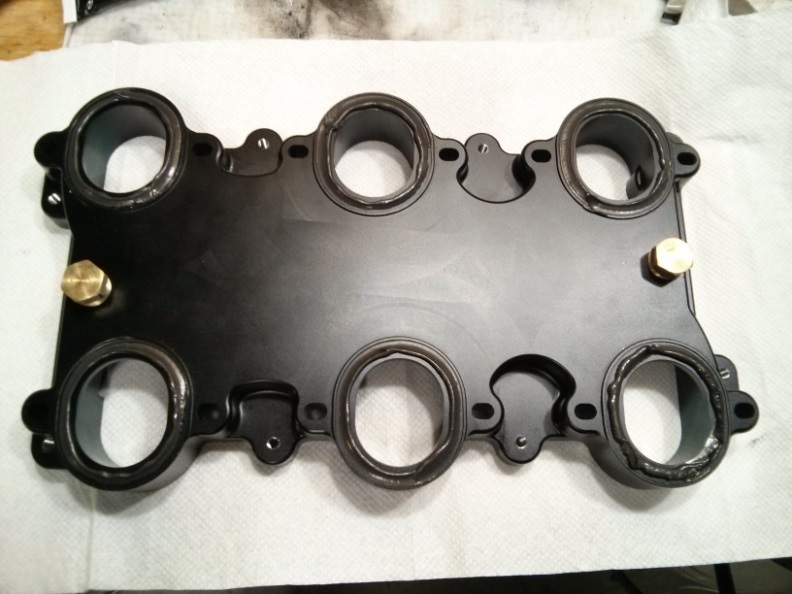
Caution! The Plenum Base Plate is NOT reversible. Before placing the Plenum Base Plate on the Engine Block, be sure the wider ridge dimension (shown below) is placed at the back of the engine bay towards the firewall. If this is reversed, your supercharger pulley will not line up with your other engine pulleys.
Optional: If you have purchased a ModdBox Intercooler Kit, remove the 1/4”NPT plugs and replace them with the provided 1/4”NPT hose fittings. Refer to the ModdBox Intercooler Kit Installation Manual for further instructions.

Place the Plenum Base Plate onto the Engine Block in the correct orientation (shown in the previous step). Align the Inlet Ports with the Plenum Bottom Plate holes. Use the supplied M6x30mm socket head cap screws and loosely bolt down the Plenum Base Plate to the Engine Block (you will need to verify the alignment of the supercharger pulley before tightening the bolts).

Place and align the Eaton M90 Supercharger and Plenum Top Plate Assembly onto the Plenum Base Plate. Visually inspect the alignment of the supercharger pulley and the other engine pulleys. A miss-alignment of approximately 1/16” is acceptable due to the length of pulley to the adjacent pulleys and the lack of ribs on the idler pulley. If the alignment of your pulley is more than approximately 1/16”, you can fine tune the alignment of the Plenum Base Plate. Simply adjust the Plenum Bottom Plate as required (they are fitted with slotted holes) and torque it down to the Engine Block.
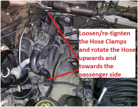
Locate the HVAC Heater Hoses (2x 1/4” diameter) that were removed from the Hose Connector Fitting and the Intake Manifold in a previous step. The hoses need to be reconnected to the Hose Connector Fitting in a new location approximately 3” above the rear-passenger side Inlet Port on the engine block (Inlet Port to combustion chamber). Review the illustration below for reference.
Cut the 1/4” diameter HVAC Heater Hose that originates from near the firewall. Be sure to leave at least a few extra inches to allow room for error. Reconnect the 1/4? diameter hose to the Hose Connector Fitting. Note: You can connect to either 1/4? barb on the fitting.


The Intake Manifold Engine Vac line (the 5/8” diameter hose that was connected to the Hose Connector Fitting and Intake Manifold) will need to be shortened and re-connected to the Hose Connector Fitting. This 5/8” Vac line consists of rubber hose AND plastic rigid tube that runs around behind the Intake Manifold. The plastic section of this line running along the firewall needs to be cut at approximately the centerline of the Intake Manifold. Reference the photo below and proceed to cut the 5/8” plastic tube. Use the provided piece of 5/8” hose (9” length) and connect one end to the 5/8” plastic line and the other to the Hose Connector Fitting. Secure both ends of the hose with a hose clamp.


(Note: the second 1/4? hose shown will be described in the next step)
Locate the remaining 1/4” diameter HVAC Heater Hose (it originates from in behind the alternator as illustrated). Remove and replace this hose with the provided 1/4” hose (24” long). Connect the other hose end to the Hose Connector Fitting. Secure both hoses with hose clamps.


Remove the rags or paper towels in your Engine Inlet Ports then proceed with the installation of the Supercharger Assembly. Apply a thin bead of Black Liquid Gasket along the Plenum Base Plate (already aligned and bolted to the Engine Block). Caution: Be sure to apply gasket material around all the bolt holes (as illustrated in the photo below). The gasket material must be extended to the inside edge of the mating face as shown on the bottom-left of the photo below. Failure to do so will result in a leak in your Intake Manifold Assembly.

(Note: Engine rags/paper towels removed from engine ports prior to installing Plenum Top Plate)
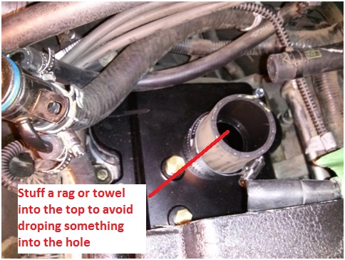
Obtain the Eaton M90 Supercharger Assembly (already assembled in a previous step). Place the assembly onto the Plenum Base Plate and bolt it down with the provided M6x30mm flange bolts. Caution: Do not drop anything into the 1 5/8” hose on the Plenum Top Plate. Debris may fall into your Engine Inlet Ports. Place a small rag or paper towel into the hose to make sure nothing falls in (make sure the rag does not fall in).
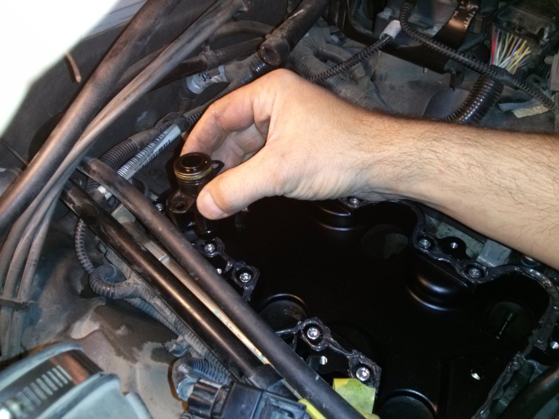
Install the stock IAC Valve on to the ModdBox Intake Manifold using the M6x12mm socket head cap screws.
Proceed with the ModdBox Intake Manifold installation by adjusting the illustrated hoses as described below.

Clear the future Throttle Cable and Cruise Control Cable location of any loose hose, ignition cables, electrical wires, fittings, etc. Be sure to fasten these components securely and away from the action of the throttle body. Caution: Failure to keep this area clear could result in your throttle sticking open! Be sure this area is kept clear and that all components in the engine bay are kept secure.

Note the orientation of the Hose Connector fitting in relationship to the ModdBox Intake Manifold.

Take the ModdBox Intake Manifold Assembly and connect the Hose Connector (already connected to two 1/4? hoses and one 5/8” hose) using the M5x10mm socket head cap screws.

Locate the Stock Throttle Cable and Cruise Control Cable (if equipped). Connect the cables to the ModdBox Cable Mount as illustrated. Snap-in the Throttle Cable to the slot on the passenger side. The Cruise Control Cable must be snapped into the driver side slot.

(Note: Contrary to the photo, it’s easier to bolt on the Throttle Body after the assembly is bolted to the supercharger)
Locate your Throttle Position Sensor Plug and Idle Air Control Valve Plug.
Carefully expose the wires from the plastic guard and electrical tape.

Take the Idle Air Control Valve Plug Wire and cut it approximately 3” from the plug end. Splice in approximately 3’ of wire to extend the wire to the new IAC location and plug it in. Use the provided tie-downs to secure the wire away from any moving parts. Caution: Make sure you do not reverse the polarity of the wires.

Apply the supplied Liquid Gasket to the ModdBox Intake Manifold as illustrated.

Line up the 1 5/8” Supercharger Bypass Hose and press the assembly down. Secure the 2” Hose Clamp to the Supercharger Bypass Valve. Caution: Do not drop anything into the Supercharger Bypass opening in the Plenum Top Plate. It may fall into an engine inlet port which could cause damage to your engine. Remove any rag or paper towel that you may have placed in the tube.

(Note: It may be easiest to have the tube connected to the Plenum Top Plate as suggested earlier)
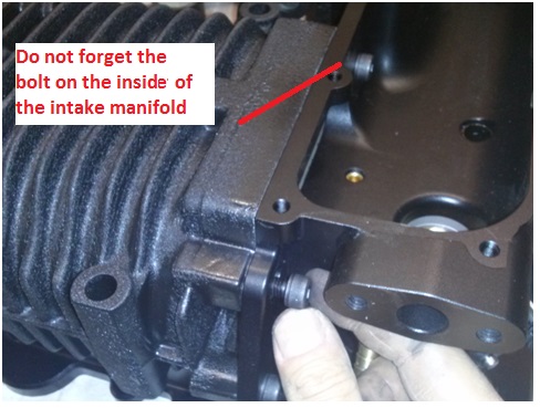
Bolt down the ModdBox Intake Manifold Assembly to the back of the supercharger using the provided M8x25mm socket head caps screws.

Bolt the Stock Throttle Body onto the the Intake Manifold as shown using the provided M6x16mm socket head caps screws.

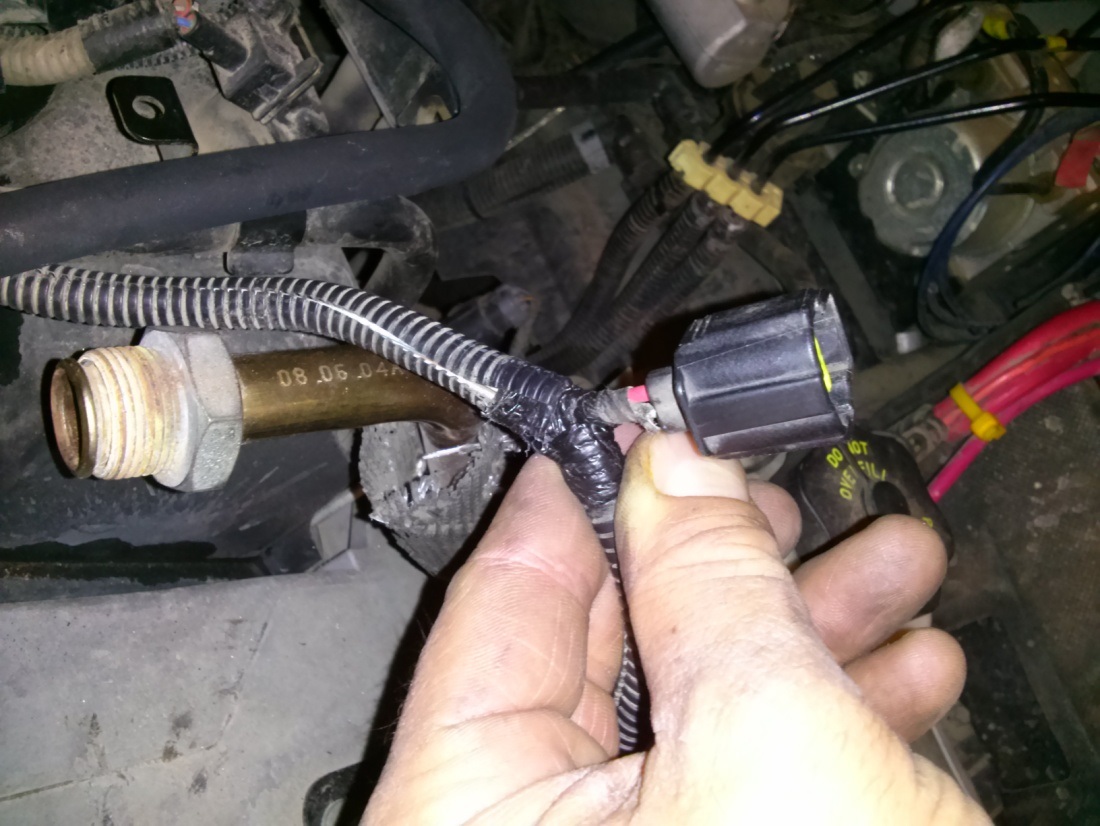
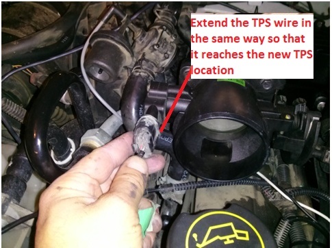
Locate the TPS plug wire and cut it approximately 3” from the plug end. Splice in approximately 3’ of wire to extend the wire to the new IAC location and plug it in. Use the provided 1/4" loom and tie-downs to secure the wire away from any moving parts. Caution: Make sure you do not reverse the polarity of the wires.
Place a thin bead of Black Liquid Gasket on the ModdBox Intake Manifold’s mating face as illustrated.

Place and bolt up the ModdBox Intake Manifold Cover with the provided M6x12mm socket head cap screws.

Locate and connect the Brake Booster Hose to the provided 3/8” barb located on the back driver side of the ModdBox Intake Manifold.

Locate the Fuel Injection Vac Line and connect it to the 3/8” barb located beside the Supercharger Bypass Valve.


Locate the Fuel Vapor Return Line. Cut off the press fit connection and reconnect it to the remaining 3/8” barb on the ModdBox Intake Manifold. Secure the hoses with the provided hose clamps.


Locate the Stock EGR Valve. Connect the valve to the provided Stainless Steel EGR Extension.

Use the provided M8x25mm bolts and secure the EGR Valve to the ModdBox Intake Manifold as illustrated.

Reconnect the EGR Vac Line.

Use the provided 5/8” hose (16” long) and connect one end to the Crank Case Ventilation Tube. The Stock Crank Case Ventilation Tube can be removed by pressing the plastic spring release on the end of the fitting.

Connect the other end of the Crank Case Vent Hose to the Stock Intake Tube. Secure both ends with a hose clamp.
Remove your vehicle’s Stock Airbox Assembly (see stock diagrams for more details). Use a saw to cut the Stock MAF Tube approximately 1” in front of the MAF mount. Re-connect the MAF tube to the Stock Intake Tube. Plug the MAF back into the electrical socket. See illustration below.
(Note: Some models will be equipped with a flange between the airbox and the MAF)
Connect the downstream side of the Stock Intake Tube to the Throttle Body. Secure both hose clamps.

Bolt the ModdBox Intake Heat Shield to the bolt located behind the passenger side headlight assembly. Secure the Intake Shield to the radiator coolant hose with the provided strap. Place your 70mm ModdBox Cold Air Intake Filter to the Stock MAF Tube and secure the hose clamp.

Replace the Stock Fuel Pump with the Moddbox 255lph Fuel Pump. See description here:
Install Instructions 4.0L V6 Cologne @ ModdBox
Re-install Radiator Rock Shield. Replace the 3/4 gallon (~3L) of coolant back to into the radiator cap.
Slack your Belt Tensioner using a 3/8” Box Wrench or Belt Removal Tool. Remove the Stock belt and replace it with the ModdBox 6PK Belt as illustrated below.
Optional. Obtain your stock throttle body cover. Cut the cover as shown in the below diagram. Remove one M6 bolt from your ModdBox Intake Manifold Cover and bolt down the throttle body cover.

CONNECTION CHECK LIST
EGR Vac Line
EGR Electrical Plug
EGR Stainless Line
Crank Case Vent Hose (may be 2 depending on your model)
IAC Electrical Plug
TPS Electrical Plug
Electrical wires (from side of Intake Manifold) should be secured away from the Throttle Cable and Cruise Control cables.
Fuel Vapor Return Line
Fuel Injection Vacuum Line
Brake Booster Line
more edits to come... for the most up-to-date information... click here:
Install Instructions 4.0L V6 Cologne @ ModdBox

So... here it goes. If you obtain a Moddbox Installation kit and any Eaton M90 supercharger (89-95 either style inlet), follow the following instructions and you're good to go. No tune required. 100% bolt-on mod. You can get your installation kit here:
ModdBoxModdBox - Engineering your driving experience @
I've also decided to post the "final result" first. If you like it.. proceed to read the "how to".
Here's a road test of the 3.5 psi pulley equipped with no cooling equipment installed.
Here's the Dyno. 215 hp & 237 lbft at the rear wheels.
Kit Photo:
Installed Photos:
TOOLS REQUIRED
Tools Required:
Standard metric socket set
Needle Nose Pliers
T-30 Torx Bit
Fluid Funnel
Flat Head Screw Driver
Punch
...will add more soon
STOCK REFERENCE DIAGRAMS
Stock Throttle Cable Reference Diagram
Stock EGR System Reference Diagram
Stock Intake Manifold Reference Diagram
Stock Air Box Reference Diagram
Stock Throttle Reference Diagram
Belt Diagram Reference Diagram (Dark Belt Showing the ModdBox Orientation)
MODDBOX SUPERCHARGER KIT PARTS
ModdBox Supercharger Bypass Valve
http://modd.me/wp-content/uploads/2013/09/CAM04401.jpg
ModdBox 255lph Fuel Pump
http://modd.me/wp-content/uploads/20...dbox255lph.jpg
ModdBox Heat Shield
http://modd.me/wp-content/uploads/20...heatShield.jpg
ModdBox 70mm Air Filter
http://modd.me/wp-content/uploads/20...yAirFilter.jpg
ModdBox Throttle Cable and Cruise Control Mount
http://modd.me/wp-content/uploads/20...eInstall-7.jpg
ModdBox 3.0 & 3.5 psi Supercharger Pulleys
http://modd.me/wp-content/uploads/2013/11/CAM04371.jpg
ModdBox Supercharger Pulley Quick Adapter
http://modd.me/wp-content/uploads/20...apterPully.jpg
ModdBox Plenum Bottom Plate
http://modd.me/wp-content/uploads/20...eInstall-9.jpg
ModdBox Plenum Top Plate
http://modd.me/wp-content/uploads/20...Install-10.jpg
ModdBox Intake Manifold
http://modd.me/wp-content/uploads/20...Install-11.jpg
ModdBox Intake Manifold Top
http://modd.me/wp-content/uploads/20...Install-12.jpg
ModdBox M22-1.5mm EGR Extension
http://modd.me/wp-content/uploads/2013/11/CAM04413.jpg
Black Silicone Liquid Gasket
http://modd.me/wp-content/uploads/2013/11/CAM04389.jpg
6pk Serpentine Belt
http://modd.me/wp-content/uploads/2013/11/6pkBelt.jpg
1/4" Electrical Loom
16 ga wire & connections
Heater Hose
Fuel Hose
Hardware and Fittings
INSTALLATION STEPS
Remove the negative battery cable (1 bolt). Secure it to the side of the battery to prevent any accidental contact with the negative terminal.
Remove the Throttle Body Cover (2 bolts). If your model is equipped with a second Crank Case Ventilation hose, you will be required to remove the hose clips on the side of the Throttle Body Cover (not shown here).
Loosen the hose clamp and disconnect the Intake Tube from the Stock Air Box Assembly.
Loosen the hose clamp and disconnect the Intake Tube from the Throttle Body.
Disconnect the Crank Case Vent Hose(s) and remove the Intake Tube. Set the Intake Tube aside for later use. Some models have a second Crank Case Vent Hose. For more information, see the Stock Setup Diagrams provided at the beginning of this instruction manual.
Remove the Brake Booster Line from the back of the Intake Manifold. Tape and label if necessary.
Unplug the cable connected to the IAC Valve.
Unbolt and remove the IAC Valve (2 bolts). Set the IAC Valve aside for later use.
Unplug the Vac line connected to the EGR. Tape and label the Vac Line if necessary.
Unbolt the EGR Valve (2 – 12mm bolts).
Remove EGR Valve by disconnecting the EGR Tube. Set the EGR Valve aside for later use.
Unplug the TPS Sensor. Tape and label the plug if necessary.
Remove the Throttle Cable from the Throttle Body Valve. The cable can be slipped free by manually actuating the valve 90 degrees and providing slack in the cable.
Unbolt the Throttle Body Valve (4 bolts). Set the Throttle Body Valve aside for later use.
Disconnect the Throttle Cable and the Cruise Control Cable.
Disconnect the electrical wire mount from the left side of the Intake Manifold.
Locate the plastic Radiator Rock Shield located underneath the engine bay. Remove the bolts and set it aside.
Locate the plastic Radiator Drain Valve at the bottom passenger side of the Radiator. Turn this plug and release only approximately a 3/4 gallon of coolant fluid (~3L). This is to allow the removal and relocation of coolant lines in the proceeding steps.
Remove the HVAC Heater Hoses (2x 1/4” diameter) and the Intake Manifold Engine Vac Line (5/8” diameter) from the Hose Connector Fitting. Tape and label the hoses if necessary.
Remove the Hose Connector Fitting. Set the Hose Connector Fitting aside for later use.
Locate the 1 5/8” diameter Radiator to Thermostat Coolant Hose.
Relocate the Coolant Hose to be in front of the Oil Cap and around the AC Line as illustrated. Cut approximately 5” to 6” off of the hose and re-secure it to the radiator.
Be sure the hose will not conflict with the belt. If not equipped with AC, secure the hose with restraining straps if necessary. Do not dispose of the 1 5/8” hose. The remaining hose will be needed in a later step.
Remove the Fuel Injection Vac Line located on the right side of the Intake Manifold. Tape and label it if necessary.
Pry off the Ignition Wire Mount located at the top of the Intake Manifold.
Unbolt the Ignition Wire Flange Mount.
With the Ignition Wire Flange Mount disconnected from the Intake Manifold, proceed to pry the Ignition Wire Flange Mount approximately 2 inches toward the driver side. This additional clearance will aid in the removal of the stock Intake Manifold as well as providing ample space for the future EGR Valve.
Unbolt the Vacuum Regulator (2 bolts) located towards the front drivers side of the Intake Manifold.
Remove the Fuel Vapor Return Line. This fitting is equipped with a simple push-style fitting. Simply push in the large curved shape and the fitting should pull off.
Remove the Throttle Cable and Cruise Control Cable Mount (2-bolts).
Loosen the Intake Manifold Bolts (12 – T30 Torx bolts). Note that these bolts do not remove completely. Once turned out of the Engine Block, the bolts remain connected to the Intake Manifold. Caution: You do not want to strip these bolts. It is advisable to inspect the Torx heads and use a vacuum to remove any dirt that may have accumulated inside the head. It may be necessary to use a machinist scribe or similar pointed object to loosen and vacuum out any dirt that may be residing inside the Torx heads before attempting to remove.
Lift out the Intake Manifold.
Caution: Do not drop anything into the Intake Ports. Before Proceeding, fill the Intake Ports with rags or paper towel. Clean and vacuum the area if necessary. Be sure to clean the Engine Block’s mating faces.
You are now ready to being modding your 4.0L J
Obtain the provided ModdBox stainless steel Supercharger Pulley Adaptor. Slip the supercharger Adapter onto your Eaton M90 Supercharger shaft until it binds (either an 89-93 oval or 94-95 rectangular style M90). The pulley is designed to have an interference fit which will cause the pulley to jam once it slips halfway onto the shaft. Use the stock Eaton M90 Supercharger lock nut to ratchet the pulley down the remaining length of the shaft until the Adapter hits the stop on the shaft. You may also want to use a press if you have one available. It is recommended that you use a low torque setting on an air or electric hammer-ratchet to suck the pulley down to the stop. If you do not have an automatic ratchet, you may carefully use a piece of soft lumber to stop the motion of the supercharger rotors. This will allow you to ratchet down the supercharger lock nut with a standard ratchet. Caution: Be sure that no debris falls into your Eaton M90 Supercharger. The tolerances on your supercharger are only a few thousandths of an inch and may be damaged if material falls or gets sucked into the supercharger housing. Even rotating the rotors by hand can often pull enough air to suck debris into the rotors. Use a vacuum to clear your rotors prior to installation.
<photo coming soon>
Obtain the provided ModdBox 6PK Custom Pulley and slip it onto the Supercharger Pulley Adaptor. Use the provided M5x16mm socket head cap screws.
<photo coming soon>
Locate the provided Black Liquid Gasket. Apply a thin bead of the gasket to the Eaton M90 Supercharger flange as illustrated.
Obtain the ModdBox Plenum Top Plate and bolt it to the base of the Eaton M90 Supercharger & Pulley Assembly. Use the provided M8x40mm socket head cap screws. Clean any excess gasket material.
Use the extra 1 5/8” diameter Radiator Hose that was remaining from a previous step. Measure out and cut a length of hose as is required for your supercharger:
For the 94’-95’ Eaton M90 Supercharger (rectangular inlet): 1-7/8”
For the 89’-93’ Eaton M90 Supercharger (oval inlet): 2-5/8”
Use one of the 2” stainless hose clamps to secure the hose to the Plenum Top Plate. Loosely place the other 2” diameter stainless hose clamp on the hose. Place the entire assembly aside for later use.
Obtain the ModdBox Plenum Base Plate. Apply a small bead of the provided Black Liquid Gasket around each Intake Port hole as shown.
Caution! The Plenum Base Plate is NOT reversible. Before placing the Plenum Base Plate on the Engine Block, be sure the wider ridge dimension (shown below) is placed at the back of the engine bay towards the firewall. If this is reversed, your supercharger pulley will not line up with your other engine pulleys.
Optional: If you have purchased a ModdBox Intercooler Kit, remove the 1/4”NPT plugs and replace them with the provided 1/4”NPT hose fittings. Refer to the ModdBox Intercooler Kit Installation Manual for further instructions.
Place the Plenum Base Plate onto the Engine Block in the correct orientation (shown in the previous step). Align the Inlet Ports with the Plenum Bottom Plate holes. Use the supplied M6x30mm socket head cap screws and loosely bolt down the Plenum Base Plate to the Engine Block (you will need to verify the alignment of the supercharger pulley before tightening the bolts).
Place and align the Eaton M90 Supercharger and Plenum Top Plate Assembly onto the Plenum Base Plate. Visually inspect the alignment of the supercharger pulley and the other engine pulleys. A miss-alignment of approximately 1/16” is acceptable due to the length of pulley to the adjacent pulleys and the lack of ribs on the idler pulley. If the alignment of your pulley is more than approximately 1/16”, you can fine tune the alignment of the Plenum Base Plate. Simply adjust the Plenum Bottom Plate as required (they are fitted with slotted holes) and torque it down to the Engine Block.
Locate the HVAC Heater Hoses (2x 1/4” diameter) that were removed from the Hose Connector Fitting and the Intake Manifold in a previous step. The hoses need to be reconnected to the Hose Connector Fitting in a new location approximately 3” above the rear-passenger side Inlet Port on the engine block (Inlet Port to combustion chamber). Review the illustration below for reference.
Cut the 1/4” diameter HVAC Heater Hose that originates from near the firewall. Be sure to leave at least a few extra inches to allow room for error. Reconnect the 1/4? diameter hose to the Hose Connector Fitting. Note: You can connect to either 1/4? barb on the fitting.
The Intake Manifold Engine Vac line (the 5/8” diameter hose that was connected to the Hose Connector Fitting and Intake Manifold) will need to be shortened and re-connected to the Hose Connector Fitting. This 5/8” Vac line consists of rubber hose AND plastic rigid tube that runs around behind the Intake Manifold. The plastic section of this line running along the firewall needs to be cut at approximately the centerline of the Intake Manifold. Reference the photo below and proceed to cut the 5/8” plastic tube. Use the provided piece of 5/8” hose (9” length) and connect one end to the 5/8” plastic line and the other to the Hose Connector Fitting. Secure both ends of the hose with a hose clamp.
(Note: the second 1/4? hose shown will be described in the next step)
Locate the remaining 1/4” diameter HVAC Heater Hose (it originates from in behind the alternator as illustrated). Remove and replace this hose with the provided 1/4” hose (24” long). Connect the other hose end to the Hose Connector Fitting. Secure both hoses with hose clamps.
Remove the rags or paper towels in your Engine Inlet Ports then proceed with the installation of the Supercharger Assembly. Apply a thin bead of Black Liquid Gasket along the Plenum Base Plate (already aligned and bolted to the Engine Block). Caution: Be sure to apply gasket material around all the bolt holes (as illustrated in the photo below). The gasket material must be extended to the inside edge of the mating face as shown on the bottom-left of the photo below. Failure to do so will result in a leak in your Intake Manifold Assembly.
(Note: Engine rags/paper towels removed from engine ports prior to installing Plenum Top Plate)
Obtain the Eaton M90 Supercharger Assembly (already assembled in a previous step). Place the assembly onto the Plenum Base Plate and bolt it down with the provided M6x30mm flange bolts. Caution: Do not drop anything into the 1 5/8” hose on the Plenum Top Plate. Debris may fall into your Engine Inlet Ports. Place a small rag or paper towel into the hose to make sure nothing falls in (make sure the rag does not fall in).
Install the stock IAC Valve on to the ModdBox Intake Manifold using the M6x12mm socket head cap screws.
Proceed with the ModdBox Intake Manifold installation by adjusting the illustrated hoses as described below.
Clear the future Throttle Cable and Cruise Control Cable location of any loose hose, ignition cables, electrical wires, fittings, etc. Be sure to fasten these components securely and away from the action of the throttle body. Caution: Failure to keep this area clear could result in your throttle sticking open! Be sure this area is kept clear and that all components in the engine bay are kept secure.
Note the orientation of the Hose Connector fitting in relationship to the ModdBox Intake Manifold.
Take the ModdBox Intake Manifold Assembly and connect the Hose Connector (already connected to two 1/4? hoses and one 5/8” hose) using the M5x10mm socket head cap screws.
Locate the Stock Throttle Cable and Cruise Control Cable (if equipped). Connect the cables to the ModdBox Cable Mount as illustrated. Snap-in the Throttle Cable to the slot on the passenger side. The Cruise Control Cable must be snapped into the driver side slot.
(Note: Contrary to the photo, it’s easier to bolt on the Throttle Body after the assembly is bolted to the supercharger)
Locate your Throttle Position Sensor Plug and Idle Air Control Valve Plug.
Carefully expose the wires from the plastic guard and electrical tape.
Take the Idle Air Control Valve Plug Wire and cut it approximately 3” from the plug end. Splice in approximately 3’ of wire to extend the wire to the new IAC location and plug it in. Use the provided tie-downs to secure the wire away from any moving parts. Caution: Make sure you do not reverse the polarity of the wires.
Apply the supplied Liquid Gasket to the ModdBox Intake Manifold as illustrated.
Line up the 1 5/8” Supercharger Bypass Hose and press the assembly down. Secure the 2” Hose Clamp to the Supercharger Bypass Valve. Caution: Do not drop anything into the Supercharger Bypass opening in the Plenum Top Plate. It may fall into an engine inlet port which could cause damage to your engine. Remove any rag or paper towel that you may have placed in the tube.
(Note: It may be easiest to have the tube connected to the Plenum Top Plate as suggested earlier)
Bolt down the ModdBox Intake Manifold Assembly to the back of the supercharger using the provided M8x25mm socket head caps screws.
Bolt the Stock Throttle Body onto the the Intake Manifold as shown using the provided M6x16mm socket head caps screws.
Locate the TPS plug wire and cut it approximately 3” from the plug end. Splice in approximately 3’ of wire to extend the wire to the new IAC location and plug it in. Use the provided 1/4" loom and tie-downs to secure the wire away from any moving parts. Caution: Make sure you do not reverse the polarity of the wires.
Place a thin bead of Black Liquid Gasket on the ModdBox Intake Manifold’s mating face as illustrated.
Place and bolt up the ModdBox Intake Manifold Cover with the provided M6x12mm socket head cap screws.
Locate and connect the Brake Booster Hose to the provided 3/8” barb located on the back driver side of the ModdBox Intake Manifold.
Locate the Fuel Injection Vac Line and connect it to the 3/8” barb located beside the Supercharger Bypass Valve.
Locate the Fuel Vapor Return Line. Cut off the press fit connection and reconnect it to the remaining 3/8” barb on the ModdBox Intake Manifold. Secure the hoses with the provided hose clamps.
Locate the Stock EGR Valve. Connect the valve to the provided Stainless Steel EGR Extension.
Use the provided M8x25mm bolts and secure the EGR Valve to the ModdBox Intake Manifold as illustrated.
Reconnect the EGR Vac Line.
Use the provided 5/8” hose (16” long) and connect one end to the Crank Case Ventilation Tube. The Stock Crank Case Ventilation Tube can be removed by pressing the plastic spring release on the end of the fitting.
Connect the other end of the Crank Case Vent Hose to the Stock Intake Tube. Secure both ends with a hose clamp.
Remove your vehicle’s Stock Airbox Assembly (see stock diagrams for more details). Use a saw to cut the Stock MAF Tube approximately 1” in front of the MAF mount. Re-connect the MAF tube to the Stock Intake Tube. Plug the MAF back into the electrical socket. See illustration below.
(Note: Some models will be equipped with a flange between the airbox and the MAF)
Connect the downstream side of the Stock Intake Tube to the Throttle Body. Secure both hose clamps.
Bolt the ModdBox Intake Heat Shield to the bolt located behind the passenger side headlight assembly. Secure the Intake Shield to the radiator coolant hose with the provided strap. Place your 70mm ModdBox Cold Air Intake Filter to the Stock MAF Tube and secure the hose clamp.
Replace the Stock Fuel Pump with the Moddbox 255lph Fuel Pump. See description here:
Install Instructions 4.0L V6 Cologne @ ModdBox
Re-install Radiator Rock Shield. Replace the 3/4 gallon (~3L) of coolant back to into the radiator cap.
Slack your Belt Tensioner using a 3/8” Box Wrench or Belt Removal Tool. Remove the Stock belt and replace it with the ModdBox 6PK Belt as illustrated below.
Optional. Obtain your stock throttle body cover. Cut the cover as shown in the below diagram. Remove one M6 bolt from your ModdBox Intake Manifold Cover and bolt down the throttle body cover.
CONNECTION CHECK LIST
EGR Vac Line
EGR Electrical Plug
EGR Stainless Line
Crank Case Vent Hose (may be 2 depending on your model)
IAC Electrical Plug
TPS Electrical Plug
Electrical wires (from side of Intake Manifold) should be secured away from the Throttle Cable and Cruise Control cables.
Fuel Vapor Return Line
Fuel Injection Vacuum Line
Brake Booster Line
more edits to come... for the most up-to-date information... click here:
Install Instructions 4.0L V6 Cologne @ ModdBox
Last edited by moddbox; 01-31-2014 at 02:50 PM. Reason: added kit photo

#5
05-16-2014, 10:31 PM
The following users liked this post:
#6
05-18-2014, 12:13 PM
Post Fiend
Join Date: Mar 2011
Location: Backwoods of Snowflake AZ
Posts: 10,080
Likes: 0
Received 2 Likes
on
2 Posts
Great write up.
This got me wondering is their any way for me to super charge a non sohc engine?
I have 2 non sohc engine propelled trucks and I think one of them would be nice to add a supercharger to. I think our 92 chassis and drivetrain with 96 body project would be the best to do this to but not sure if it is possible?
Trav
#7
05-18-2014, 11:42 PM
Anything is possible. However, even this kit is (while fairly professional and they try to be well put together), it is also a hack.
Firstly, since this kit does not replace any internal parts, there are some issues. The first part is that you are running the stock pistons, which are not forged. Whats the danger in that? Well, hyperturetic pistons are cast using a method that allows them to increase the silica content beyond the normal allowable limits. This makes a piston that is reasonably durable with a low index of expansion. This is great for a stock setup. But boost adds heat. If you overheat a hypertuertic piston, they can crack or shatter, or they can melt. Since you are only running a few lbs boost, that is how they get away with it, but if anything goes wrong, like a plugged injector, a bad MAF sensor, a plugged fuel filter, etc. it can cause serious engine damage.
A proper turbo or supercharger build would use a forged piston, preferably that is either dished or has a lower profile, so that it reduces the compression ratio.
Second hack area is the use of a FMU. The FMU basically defeats the lack of adaptability by increasing the fuel pressure at a non-linear rate as boost increases. This in turn increases flow through the injectors, and helps prevent the mixture from going lean during boost. There are some downsides to this approach as well. Firstly, it increases the strain on the fuel pump, and as pressure increases, flow decreases, which can actually reduce flow during high demand, the exact opposite of what you want to happen. The FMU does nothing to correct timing for boost.
The proper way to do it is to used a fixed rate pressure regulator that increases fuel pressure in a linear fashion, i.e. 1 psi increase in fuel pressure for each lb. boost. The the enrichment is handled in tuning. When properly tuned the computer knows the throttle position, and is tuned for the increase in flow and boost, and will richen the mixture accordingly, and will properly reduce timing during peak boost onset.
I think this kit is very nice, but I would never just slap in on my vehicle. I have built turbo motors, and know how to do it properly, and I know what happens when you shortcut and use the kinds of gimmicks that this kit does.
To do a 4.0L OHV, there are no bolt on kits still in production, so you would need to have stuff fabricated. But it is doable. The realistic truth is, if you want a durable and reliable setup, you will need to shell out several grand.
Trending Topics
#8
05-19-2014, 11:40 AM
@KhanTyranitar
Thanks for your comments. As someone who obviously has some experience with boosting, you bring up some great points for those who are might not be experts on the 4.0L SOHC.
Regarding your comment about the stock pistons, you are correct. It is ideal to have a forged aftermarket piston preferably with lower compression ratio (say 9:1) when applying high boost to 4.0L SOHC (whether by turboing or supercharging). However, the stock pistons are more than adequate up to around 8psi boost.
You mentioned "but if anything goes wrong, like a plugged injector, a bad MAF sensor, a plugged fuel filter, etc. it can cause serious engine damage"... that would be the case no matter what you kind of pistons you have or whatever the level of boost you are running. Even a naturally aspirated engine will break down and overheat if you are leaning out.
Your second point was regarding fuel delivery. We include a 255lph fuel pump and as a Engineer with specialization if fluid dynamics I can tell you that the fuel pump is more than adequate and it will not be strained. Also, the stock fuel regulator produces a static 60-65psi at the fuel rail. I agree that a "fixed rate pressure regulator" or a rising fuel pressure regulator (for those of you who are not familiar) is ideal. However, the lower boost applications can hardly justify it. Even at the 8psi boost, the pressure across the injectors is still around 55psi (eg. 63psi fuel rail - 8psi boost = 55 psi). ~4 bar of fuel pressure across the injector is more than adequate for safely tuning your vehicle.
Regarding tuning, we have teamed up with Lasota Racing in Ohio and they provide tuning services for all our customers. With their long history in tuning and experience with SCT, they are the best in the business. We are lucky to be working with such highly experienced and respected people in this business.
PS.
There are many turbo/SC kits on the market for the 4.0L SOHC that provide boosts up to ~8psi and do not recommend or suggest any changes to the internals for a reason. But for those of us who have more money to spend and want to go much farther with boosting the 4.0L SOHC, I would suggest doing the changes that KhanTyranitar suggests.

Thread
Thread Starter
Forum
Replies
Last Post
gabriell12123
1999 to 2016 Super Duty
3
05-29-2018 07:12 AM
sammie0126
Excursion - King of SUVs
26
11-24-2015 02:00 PM
moddbox
Explorer, Sport Trac, Mountaineer & Aviator
7
05-26-2014 11:12 PM
moddbox
Supercharger, Turbocharger, Nitrous Oxide & Water/Methanol Injection
1
05-16-2014 10:31 PM