FABRICATION!! We want to see what you've built.

#17
 10-24-2013, 02:44 PM
Posting Guru
Join Date: Apr 2013
Location: Rimrock AZ
Posts: 1,170
Likes: 0
Received 0 Likes
on
0 Posts
#18
10-24-2013, 02:54 PM

Lead Driver

#19
10-24-2013, 03:41 PM
Any details on the metal brake? Looks good. I built a brake based on something from a Mother Earth News magazine about 30 years ago but it's not quite as refined as yours appears to be.
#20
10-24-2013, 04:05 PM
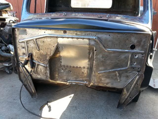
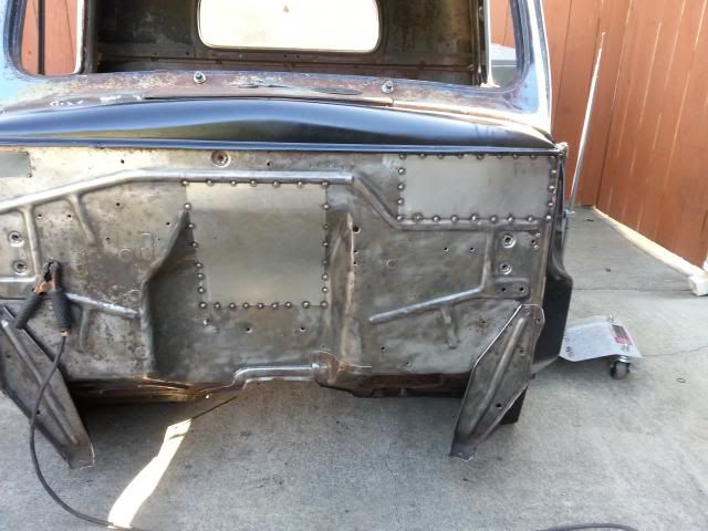
+1 Mike and Joe's comment about the fabulous fab projects some here have done. My examples are like Doods54. But I'll post my hanging brake pedal bracket. From a 77 Chevy with extension top and bottom to get to the top and bottom fire wall pinch seams and a strut to the bottom of the dash. Seems plenty stout. Some day I might remove the arm, cut off the pedal and weld on a heavy nut to attach the oem pedal.

#22
10-24-2013, 07:08 PM


#23
10-24-2013, 08:12 PM


Actually I was just kinda winging it.....it is pretty simply built, the base is a couple pieces of 8" channel. The clamp is a piece of grader blade (cutting edge), and the tipping blade is 5/8x 4". Spring loaded clamps are large bolts.
#26
10-25-2013, 12:06 AM
I have several fabrication projects documented in my galleries (click on my user name at the top of any of my posts, select view gallery, select appropriate gallery) but here's one reposted:
Repro LED caddy tailights frenched in the rear fenders of my 56 panel
1. building 16 ga bucket around wood buck

2. Making sure top is same size/shape as bottom after welding:

3. Frame ready to have base welded in:

4. Wood buck, LED taillight, finished bucket:

5.Deciding on placement:

6. Body opening cut. Note raised OEM taillight mount area not yet shaved, filled.

7. Bucket inset and angle determined, body line traced on outside of bucket:

8. Bucket skip tacked to body opening:

9, Original raised mount area cut away, shaped patch fitted:

10. bucket and patch completely welded, excess bucket ground smooth, inside corners being rounded with die grinder:

11. Locating any high or low spots with body (vixen) file:

12. Metal finishing nearly complete. Just a couple small low spots to raise up and a skim coat of putty to finish.

13. Pass side done same way. Test fitting taillight:

Repro LED caddy tailights frenched in the rear fenders of my 56 panel
1. building 16 ga bucket around wood buck
2. Making sure top is same size/shape as bottom after welding:
3. Frame ready to have base welded in:
4. Wood buck, LED taillight, finished bucket:
5.Deciding on placement:
6. Body opening cut. Note raised OEM taillight mount area not yet shaved, filled.
7. Bucket inset and angle determined, body line traced on outside of bucket:
8. Bucket skip tacked to body opening:
9, Original raised mount area cut away, shaped patch fitted:
10. bucket and patch completely welded, excess bucket ground smooth, inside corners being rounded with die grinder:
11. Locating any high or low spots with body (vixen) file:
12. Metal finishing nearly complete. Just a couple small low spots to raise up and a skim coat of putty to finish.
13. Pass side done same way. Test fitting taillight:
#28
10-25-2013, 09:51 AM
[quote=AXracer;13664665]I have several fabrication projects documented in my galleries (click on my user name at the top of any of my posts, select view gallery, select appropriate gallery) but here's one reposted:
Ax, thanks for the re-post. I've spent countless hours going through galleries looking for fabrication projects like yours and I thought this thread would highlight a variety of fabrication projects done by different builders.
I know that there are a lot of interesting fabrication projects hidden in the galleries, but I don't get a lot of positive results using the search features.
#29
10-25-2013, 11:06 AM
Installed a sterling 10 1/4 rear from a '92 F350 under my '59 F350. Had to move the existing spring mounts about 1 1/2", while keeping same driveline angle. Then I modified the driveshaft length by using about 10" of the '92s shaft telescoped over the cut-off end of the 59's. The eight 1/4-20 round head stove bolts provided perfect spacers for aligning the two. I could not slide them together without light tapping with a brass hammer. At the open end where dissimilar diameters presented a welding challange, I took a ring off a piece of steel pipe and removed the weld line inside with a die grinder, then tapped it up the smaller shaft. I tacked it in place and needed to taper this ring so it would engage part way into the larger shaft. There was a 4 speed 'lathe', powered by a six cylinder engine mounted in just the right place. Thus, I engaged second gear and using an angle grinder, tapered my ring with a trial and error fit. Next, being very careful to keep the u-joins in sync, I welded it up. The inside of the ring to the small shaft, the outside of the ring to the larger shaft. I know driveline work is fairly cheap, but so am I. As for safety, all I can think of for failure is my weld fails, and the two shafts slide within each other and I roll to a stop. Thinking a 3" dia shaft has about 9"+ of weld around it to shear. At 60, no vibration I can detect......


