
How to replace pinion bearings and carrier/side bearings in 10.5 inch rear differential
#1
 09-22-2013, 09:20 PM


How to replace pinion bearings and carrier/side bearings in 10.5 inch rear differential
Press Old Bearing Cones Off and New Bearing Cones On
Now you go to any local shop with a hydraulic press (preferably a transmission shop) and pay the guy a few bucks to pull off and press in 3 bearings. The front pinion bearing just slides over the pinion shaft. No pressing required. You’ll be in and out in 30 minutes.
Carrier Bearings:
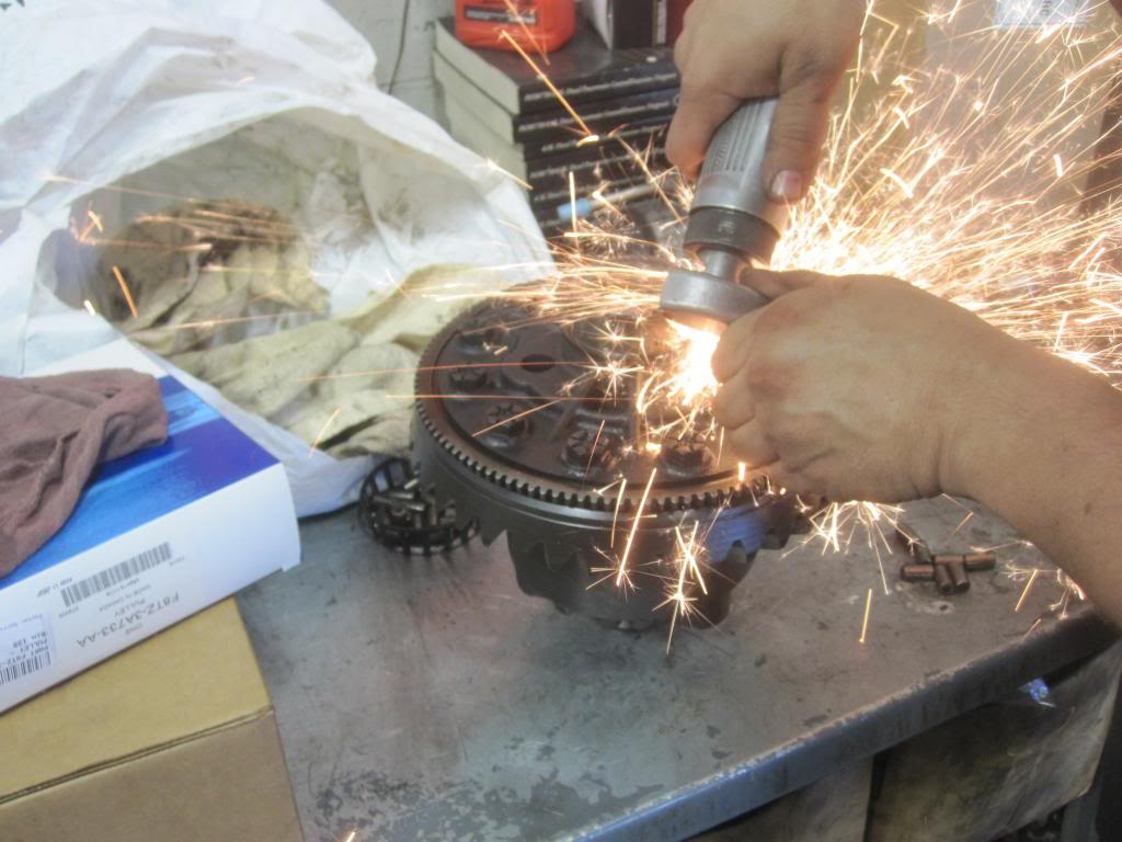
I got some help today pressing the 3 (of 4) new bearings in place. So I thought they would use the hydraulic press and gear puller to pull the old bearings off but the Ford guys said it’s easier to cut them off! Hey hey hey why do they get to have all the fun....!? I coulda done that at home. I figured they would take them off the "right way" since they have a press. So now you know...even some pros prefer to cut them off.
Since they are on so tight, once you compromise them they tend to crack open and you can pull them off or use an air hammer to knock them off.
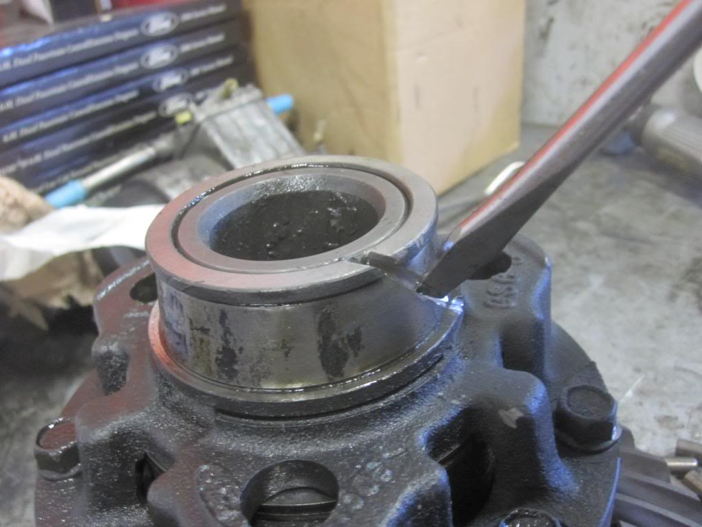
Here is the procedure: Cut the outer housing off. Make sure you cover up the diff so metal pieces don’t get into it if you cut yours off as well. (Yes I see all the metal bits...not good. I will be rinsing the parts with some brake parts cleaner).
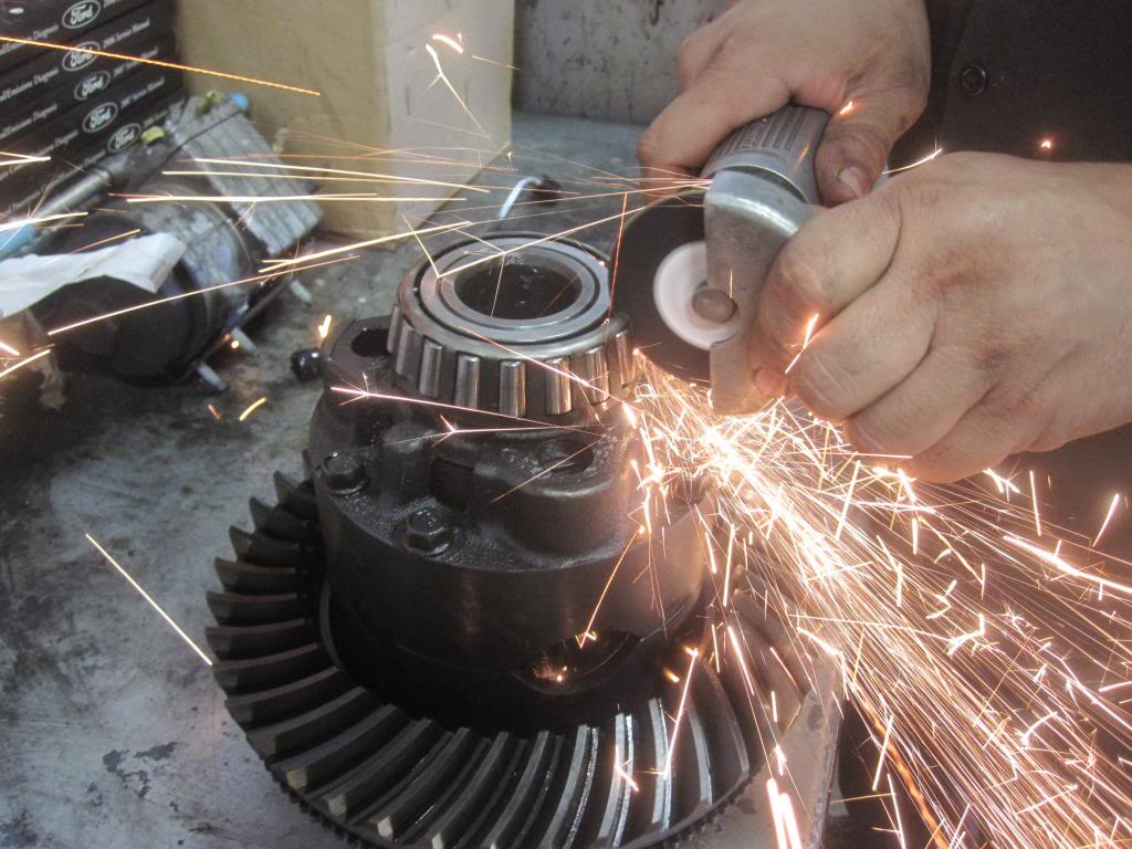
It will look like this:
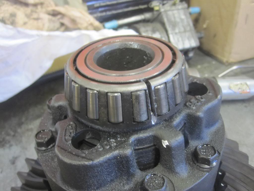
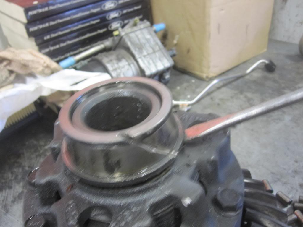
Break the outer part of the bearing off with a screw driver and hammer. Then you have the inner part of the bearing left to cut off:
BTW look how pitted the inner bearing is. They said this would tend to make lots or rumble at speed but not the high pitched noise I was hearing, which would be caused by pinion bearings or in my case, spun carrier bearings.
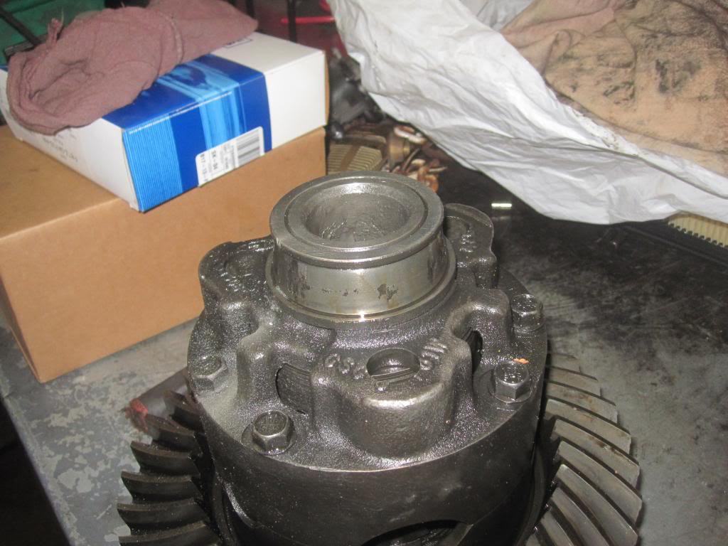
Now you cut the inner part of the bearing. Don’t worry if you slightly nick the shaft of the differential that the bearing sits on. They said it’s not an issue since 1. The rollers don’t touch that face and 2. it takes so much pressure to get those bearings on the shaft that they aren’t going anywhere even if you nick them.
Now just pry it off or use an air hammer on the upper lip to knock it off.
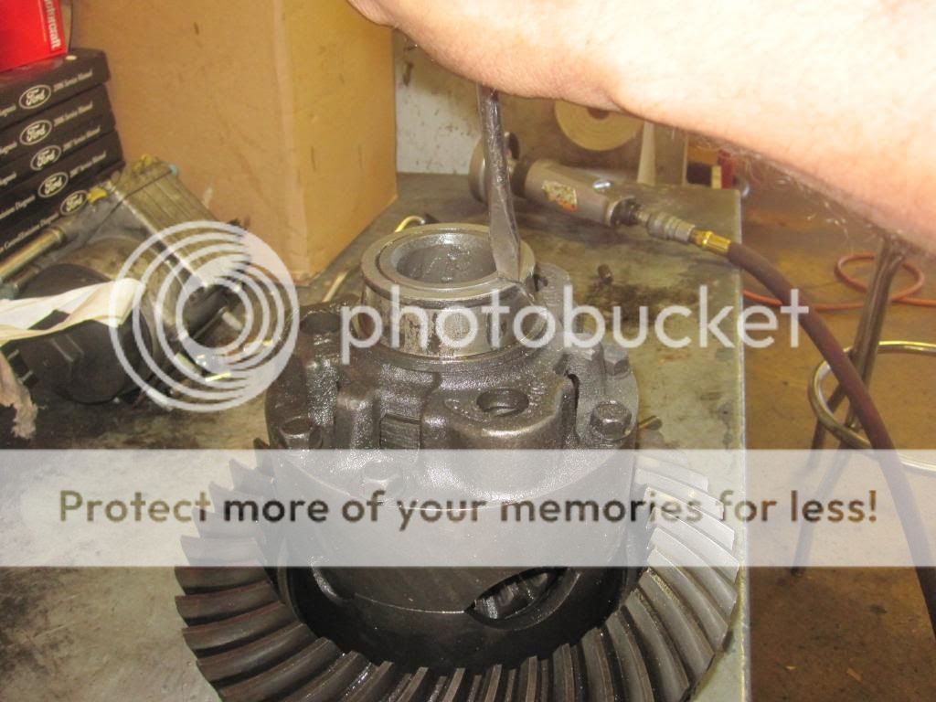
Now you cut the carrier bearing on the other side.
and then you get this: (getting bored yet?)
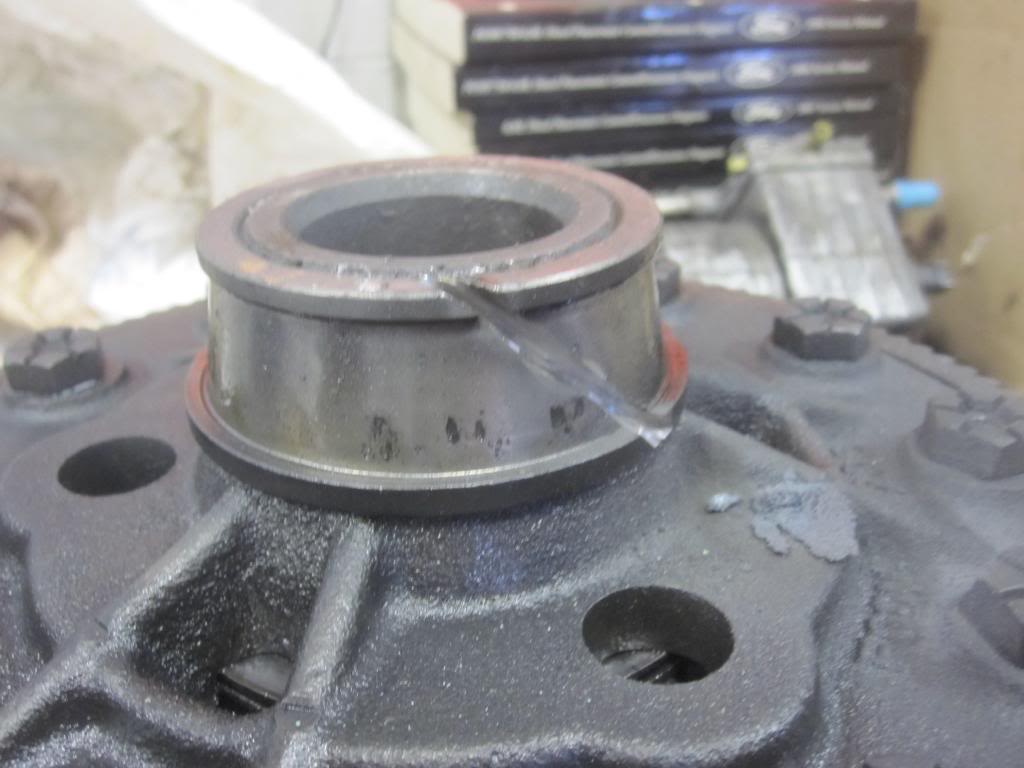
Break it with the screwdriver and hammer as below and off it comes:
Look at just how pitted the bearing was:
 ;
;
Now you go to any local shop with a hydraulic press (preferably a transmission shop) and pay the guy a few bucks to pull off and press in 3 bearings. The front pinion bearing just slides over the pinion shaft. No pressing required. You’ll be in and out in 30 minutes.
Carrier Bearings:
I got some help today pressing the 3 (of 4) new bearings in place. So I thought they would use the hydraulic press and gear puller to pull the old bearings off but the Ford guys said it’s easier to cut them off! Hey hey hey why do they get to have all the fun....!? I coulda done that at home. I figured they would take them off the "right way" since they have a press. So now you know...even some pros prefer to cut them off.
Since they are on so tight, once you compromise them they tend to crack open and you can pull them off or use an air hammer to knock them off.
Here is the procedure: Cut the outer housing off. Make sure you cover up the diff so metal pieces don’t get into it if you cut yours off as well. (Yes I see all the metal bits...not good. I will be rinsing the parts with some brake parts cleaner).
It will look like this:
Break the outer part of the bearing off with a screw driver and hammer. Then you have the inner part of the bearing left to cut off:
BTW look how pitted the inner bearing is. They said this would tend to make lots or rumble at speed but not the high pitched noise I was hearing, which would be caused by pinion bearings or in my case, spun carrier bearings.
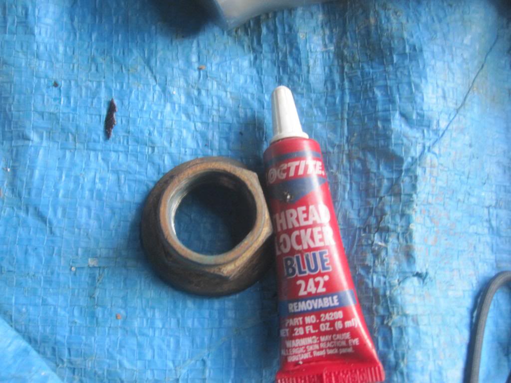
Now you cut the inner part of the bearing. Don’t worry if you slightly nick the shaft of the differential that the bearing sits on. They said it’s not an issue since 1. The rollers don’t touch that face and 2. it takes so much pressure to get those bearings on the shaft that they aren’t going anywhere even if you nick them.
Now just pry it off or use an air hammer on the upper lip to knock it off.
Now you cut the carrier bearing on the other side.
and then you get this: (getting bored yet?)
Break it with the screwdriver and hammer as below and off it comes:
Look at just how pitted the bearing was:
Last edited by Stewart_H; 11-21-2013 at 11:11 PM.
#2
09-22-2013, 09:20 PM
How to replace pinion bearings and carrier/side bearings in 10.5 inch rear differential
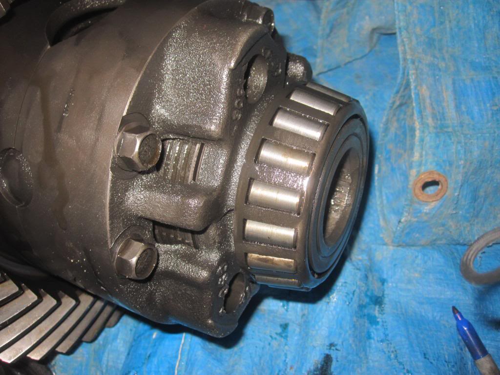
Pinion Bearing (Rear):
Now onto the pinion bearing...which I didn’t get pictures of during cutting process, but it did come off perhaps a little too easily they said. This might be part of the cause of the loud whining noise I am getting when accelerating.
Here is the rearward pinion bearing with the outer part of the bearing cut off and the inner part of the bearing just sitting on the shaft. NOTE that there is a very thin spacer/shim under the rearward pinion bearing right against the pinion gear. DONT LOSE IT. I show a picture of it below.
Here is the bare pinion shaft and gear.
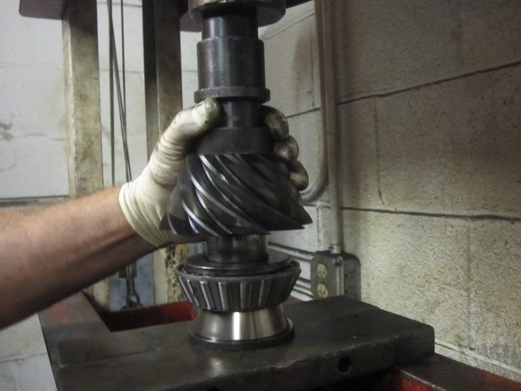
And now the part I really needed help with....the pressing of the bearings. This was superfast. It took maybe 10 minutes with the press and some experience.
I know sometimes bearings are heated to 250-270 degrees F to expand them and the housing is cooled/contracted so that you don’t need to use any press at all.
Example:
I don’t know how well this would work for this application and whether or not freezing the differential would also be required. Some use dry ice I am told. Anyway I decided not to experiment...
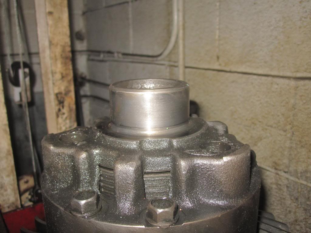
This is the rearward pinion bearing being pressed into place until it bottoms out. See how they used the old inner part of the bearing to support the new bearing?:
Note YOU MUST REUSE THE SUPER SKINNY SHIM BETWEEN the pinion gear and the new bearing!!! I am holding it up with the screw driver in this pic:
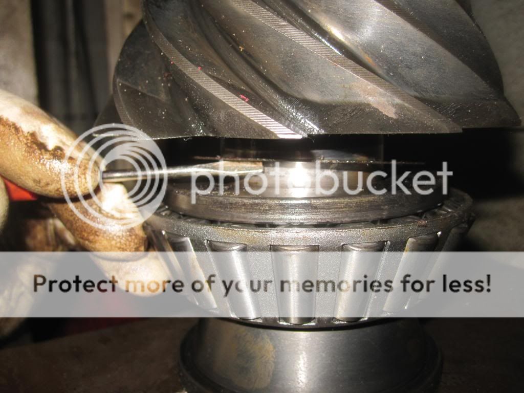
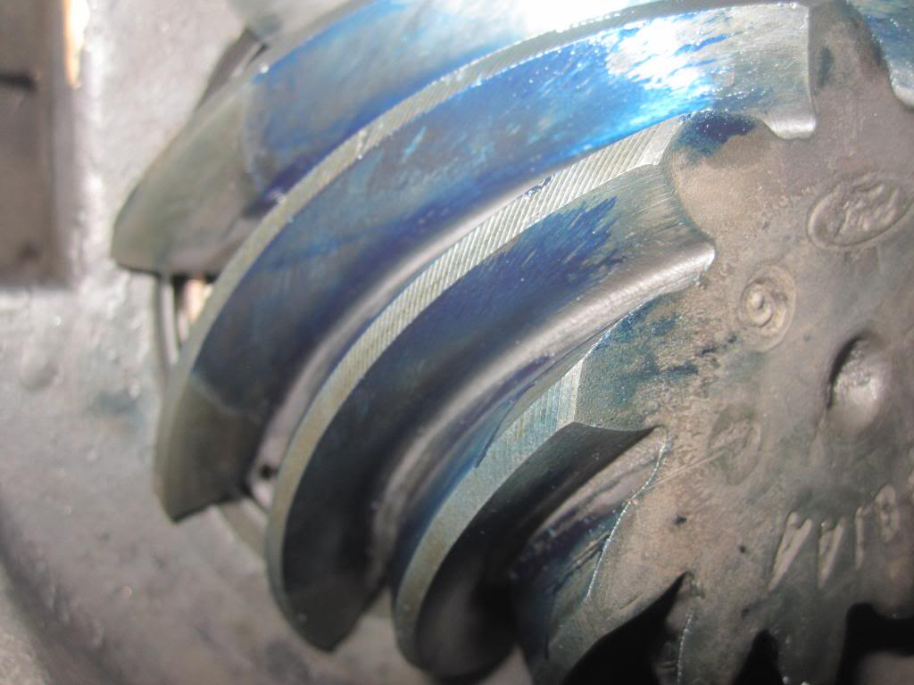
In the pic above, the mechanics pointed out that the wear pattern on the pinion gear is very good. In other words the ring gear is making contact along the middle of the pinion teeth and not the edges of the teeth. You can see that because of the wear pattern on the pinion (see the dark versus shiny part of the pinion gear teeth?).
This explanation is for the ring gear teeth but the idea is the same:
This explanation is helpful as well: http://departments.weber.edu/automot...rpretation.pdf
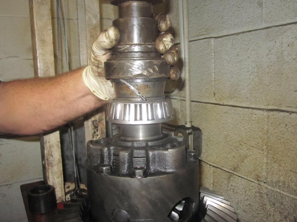
And now the new driver's side carrier bearing gets pressed into place:
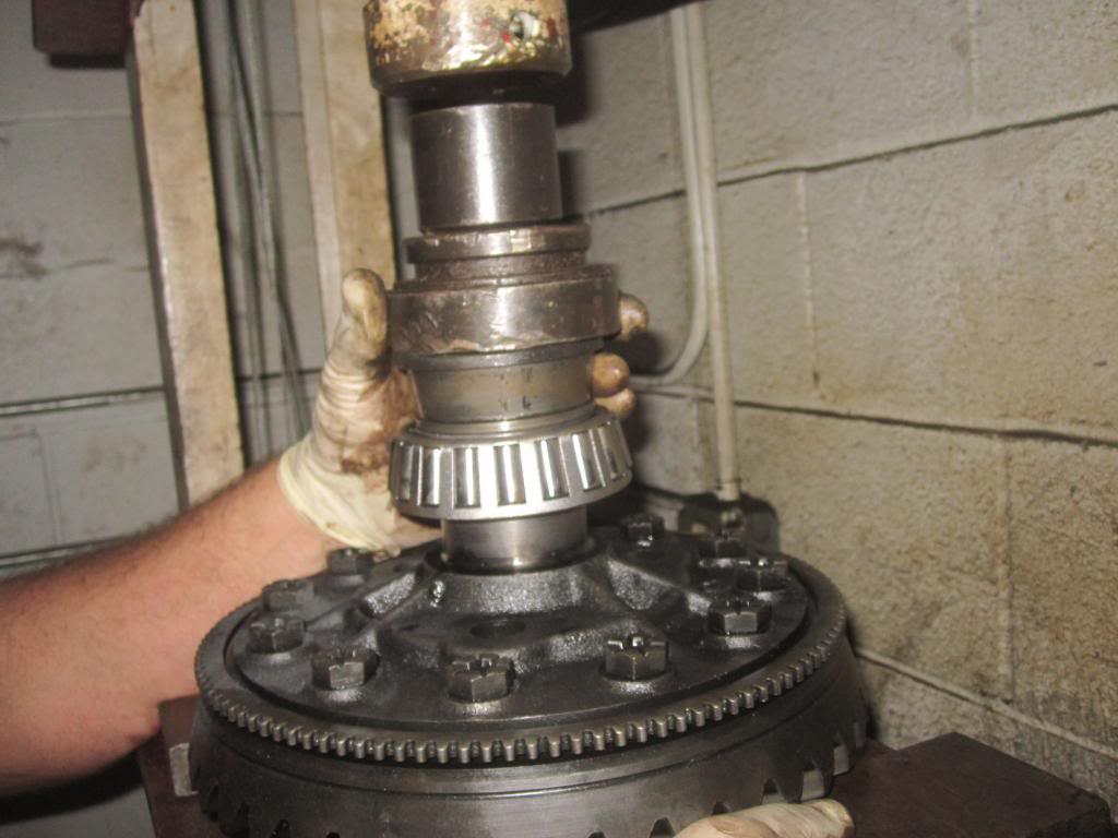
...and the passenger's side gets pressed into place. Here is the shaft before accepting the new bearing.
and being pressed in place:
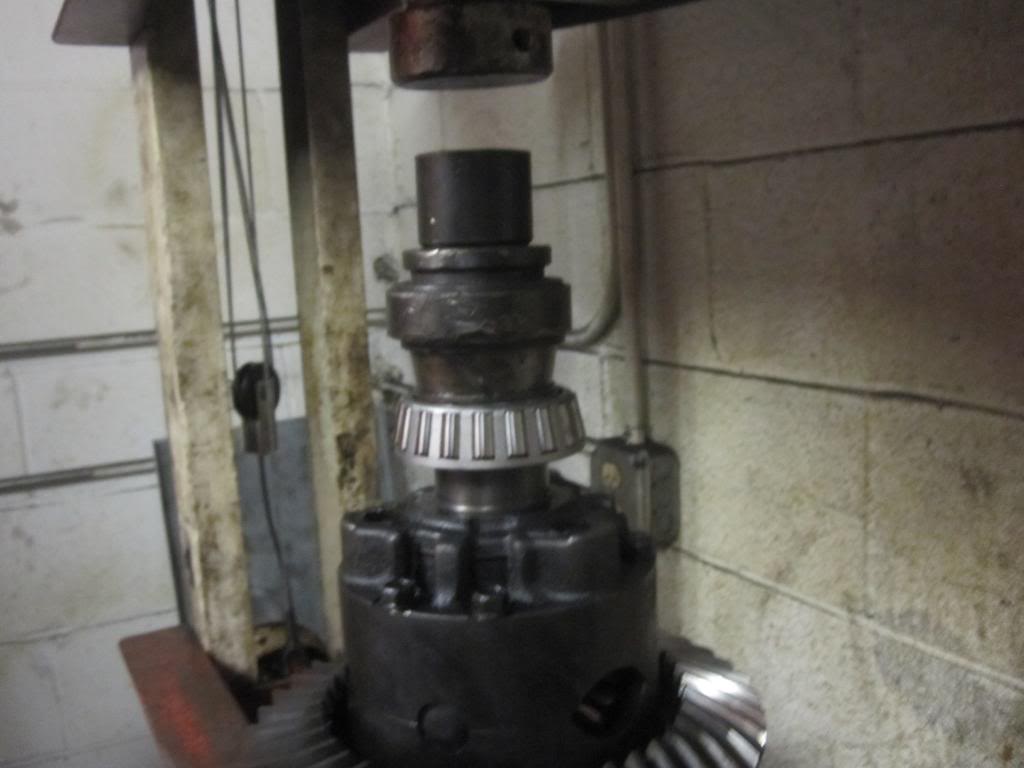
...and one more shot of the same (see how the old cut inner part of the bearing is used as to help push the new bearing into place?):
Remove the Pinion Cups / Races
Now, back under the truck to remove and replace the two pinion bearing races/cups. Removal is super easy. You just bang them out. There are even two cut-outs in the differential case to allow easier access to the back of each race. See them here in the case of the front pinion bearing race:
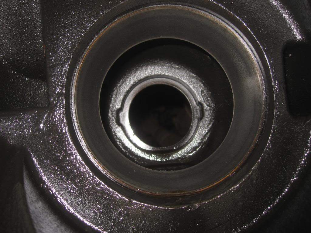
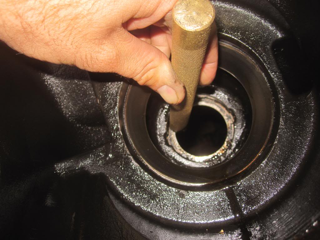
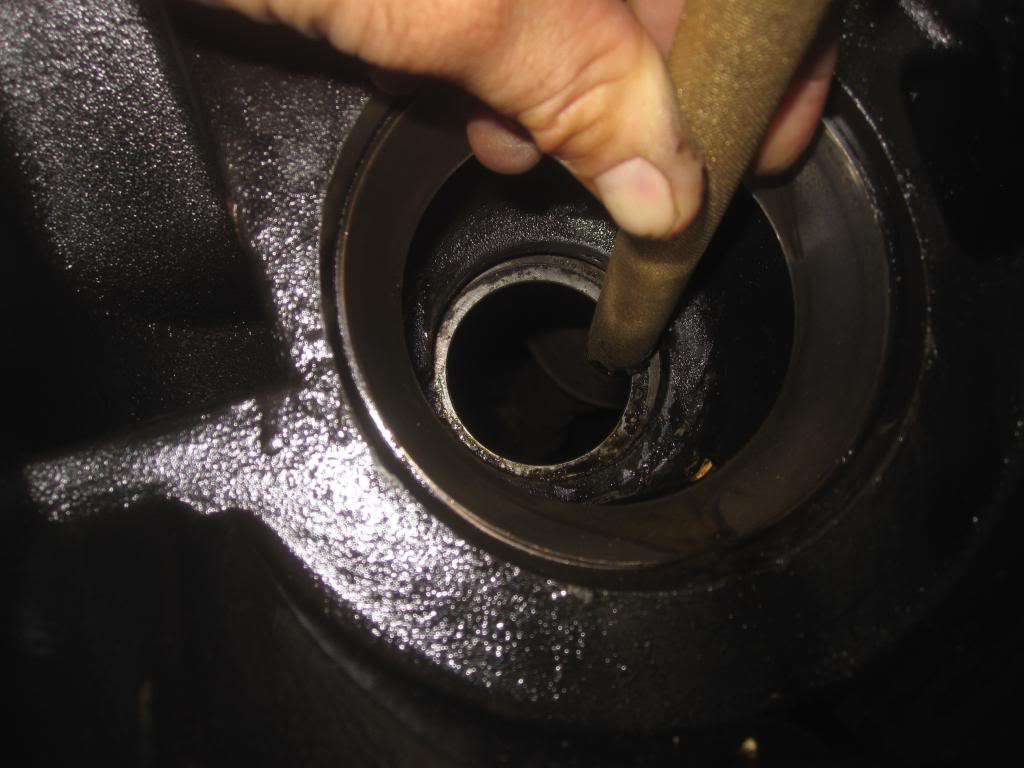
You could use a large screwdriver or metal bar, maybe even an air hammer with a chisel bit to tap out the old race. I bought a set of brass drifts (brass bars) which are softer than the bearings, races or the differential case so as to not scratch any surfaces accidentally. I used a 3 pound short handled sledgehammer as well.
Actually you need one large drift preferably 10 -12 inches long because the pinion race is deep inside the housing. My largest drift is only maybe 8-ish inches, which meant I had to swing the sledge inside the differential to get the front race off as opposed to being able to swing the sledge outside of it which would have been easier. Either way, it’s no big deal. If you don’t have a brass drift just make sure you don’t scratch the walls (the bore) of the case where the races sit.
BTW, I tried a long piece of pressure treated wood but it didn’t do very well. Its too soft and not enough surface area for it to bite into.
Here I alternate smacking on each side of the front race from the back of the differential.
Ok so once you've pounded the front pinion race out (from behind) then you have the naked bore:
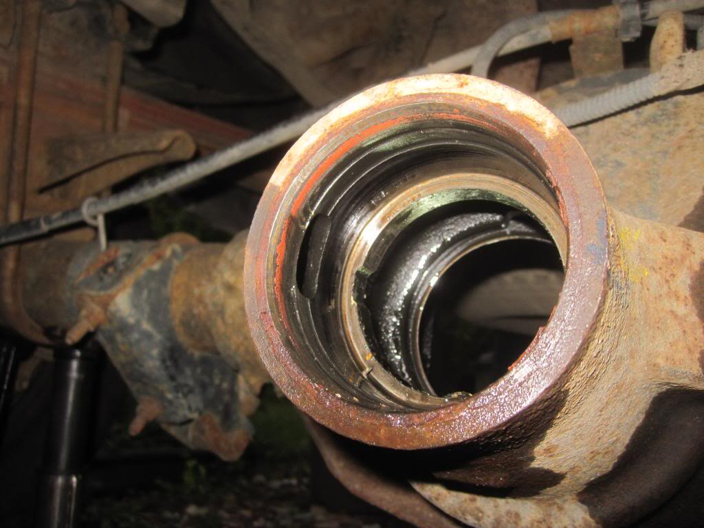
Then move to the front of the diff and pound the rear pinion bearing race out towards the rear of the truck. Same technique. This race is easier because you're not trying to swing a hammer inside the differential case. It has the same cut-outs to give you better access to the back of the race so you can smack it out. See (hey what are those garbage bins doing in my diff?):
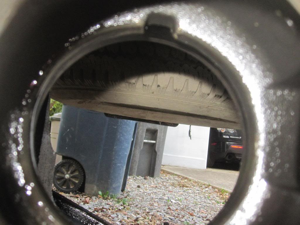
At first they don’t wanna move but after a few heavy smack they will come out. Fear not.
Now onto the pinion bearing...which I didn’t get pictures of during cutting process, but it did come off perhaps a little too easily they said. This might be part of the cause of the loud whining noise I am getting when accelerating.
Here is the rearward pinion bearing with the outer part of the bearing cut off and the inner part of the bearing just sitting on the shaft. NOTE that there is a very thin spacer/shim under the rearward pinion bearing right against the pinion gear. DONT LOSE IT. I show a picture of it below.
Here is the bare pinion shaft and gear.
And now the part I really needed help with....the pressing of the bearings. This was superfast. It took maybe 10 minutes with the press and some experience.
I know sometimes bearings are heated to 250-270 degrees F to expand them and the housing is cooled/contracted so that you don’t need to use any press at all.
Example:
I don’t know how well this would work for this application and whether or not freezing the differential would also be required. Some use dry ice I am told. Anyway I decided not to experiment...
This is the rearward pinion bearing being pressed into place until it bottoms out. See how they used the old inner part of the bearing to support the new bearing?:
Note YOU MUST REUSE THE SUPER SKINNY SHIM BETWEEN the pinion gear and the new bearing!!! I am holding it up with the screw driver in this pic:
In the pic above, the mechanics pointed out that the wear pattern on the pinion gear is very good. In other words the ring gear is making contact along the middle of the pinion teeth and not the edges of the teeth. You can see that because of the wear pattern on the pinion (see the dark versus shiny part of the pinion gear teeth?).
This explanation is for the ring gear teeth but the idea is the same:
This explanation is helpful as well: http://departments.weber.edu/automot...rpretation.pdf
And now the new driver's side carrier bearing gets pressed into place:
...and the passenger's side gets pressed into place. Here is the shaft before accepting the new bearing.
and being pressed in place:
...and one more shot of the same (see how the old cut inner part of the bearing is used as to help push the new bearing into place?):
Remove the Pinion Cups / Races
Now, back under the truck to remove and replace the two pinion bearing races/cups. Removal is super easy. You just bang them out. There are even two cut-outs in the differential case to allow easier access to the back of each race. See them here in the case of the front pinion bearing race:
You could use a large screwdriver or metal bar, maybe even an air hammer with a chisel bit to tap out the old race. I bought a set of brass drifts (brass bars) which are softer than the bearings, races or the differential case so as to not scratch any surfaces accidentally. I used a 3 pound short handled sledgehammer as well.
Actually you need one large drift preferably 10 -12 inches long because the pinion race is deep inside the housing. My largest drift is only maybe 8-ish inches, which meant I had to swing the sledge inside the differential to get the front race off as opposed to being able to swing the sledge outside of it which would have been easier. Either way, it’s no big deal. If you don’t have a brass drift just make sure you don’t scratch the walls (the bore) of the case where the races sit.
BTW, I tried a long piece of pressure treated wood but it didn’t do very well. Its too soft and not enough surface area for it to bite into.
Here I alternate smacking on each side of the front race from the back of the differential.
Ok so once you've pounded the front pinion race out (from behind) then you have the naked bore:
Then move to the front of the diff and pound the rear pinion bearing race out towards the rear of the truck. Same technique. This race is easier because you're not trying to swing a hammer inside the differential case. It has the same cut-outs to give you better access to the back of the race so you can smack it out. See (hey what are those garbage bins doing in my diff?):
At first they don’t wanna move but after a few heavy smack they will come out. Fear not.
Last edited by Stewart_H; 11-21-2013 at 11:12 PM.
#3
09-22-2013, 09:20 PM
How to replace pinion bearings and carrier/side bearings in 10.5 inch rear differential
Installing New Races
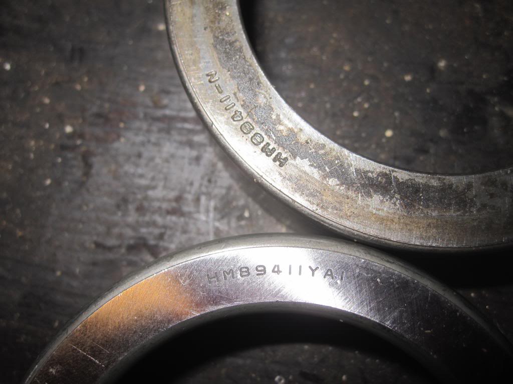
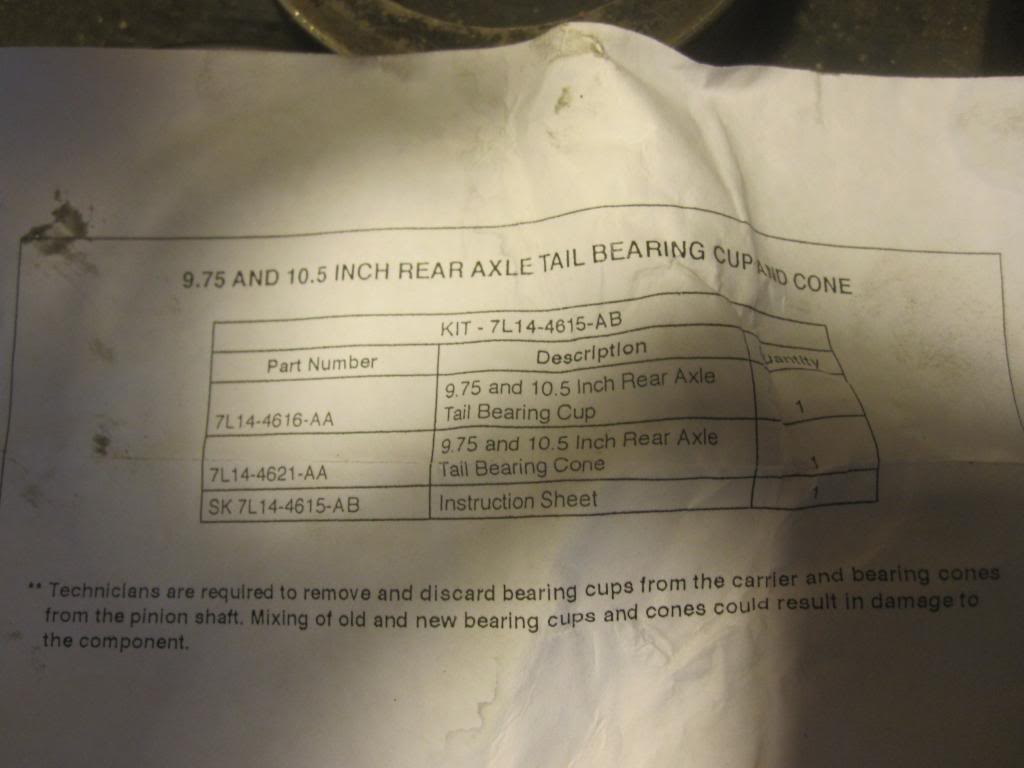
Now take a rag and wipe all the surfaces clean in preparation for the new races. This is some precision fit stuff. I got a little nervous when the front pinion race (this bearing and race come together as a unit in one box) didn’t have the exact same serial # etched into the back of it as the old race, but it fit. The accompanying paperwork indicated that it was for the 10.5.
You'll need a bearing/race installer kit. You can borrow one from Advance Auto or AutoZone or whomever. They aren’t expensive if you need to buy one. Maybe $40. They are made of aluminum so you don’t scratch the race surface as you smack it into place. You can use it with a sledge hammer or air chisel attachment. I used both. The sledge to start the new race into place, then the air chisel attachment to finish it.
Now just take the new race and push it into place by hand to get it started. It will stay in place.
Here is the race installer being placed over the new rear pinion race. Yes I know, the head of the tool is on backwards in this photo. It should go the other way.
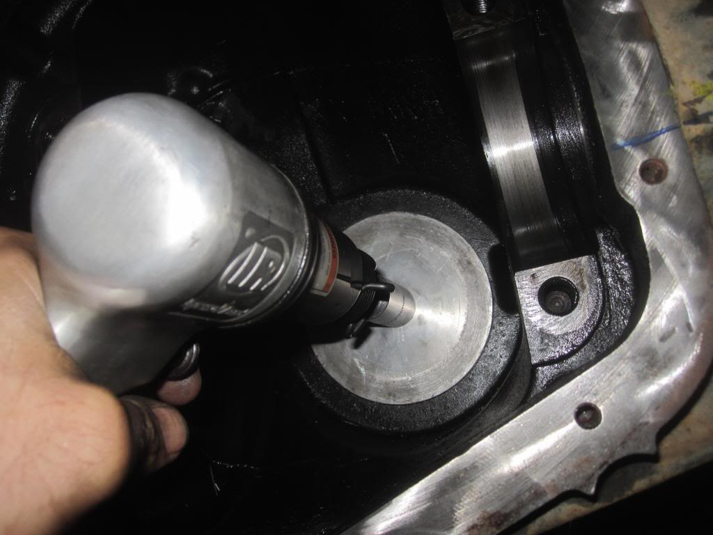
Just seat it so it’s square and then start pounding. Smack the **** out of it. Just don’t hit anything in the differential case. Like I said above I used the air hammer/chisel after I had it in square, and it worked like a CHAMP. See here (I wasn’t sure if the tool was going to be too big...it just barely fit):
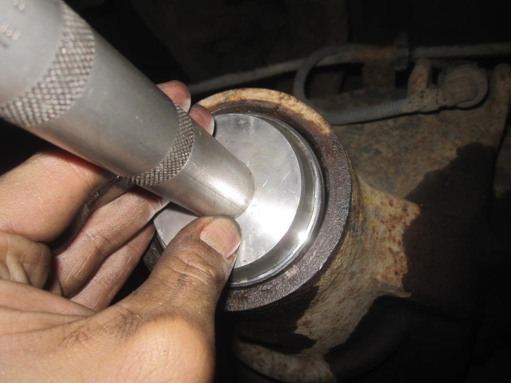
The manual says to take a feeler gauge to make sure you’ve pushed (seated) the new race all the way. I suggest you do so.
It’s pretty obvious when it’s seated. But smack it a few dozen extra times to be sure. That's what the mechanics at Ford told me they do.
Now take your 0.0015 of inch feeler gauge (a set are cheap at any auto parts store...$7) and make sure you seated the cups/races in all the way. If ya can’t jam it in between the back of the cups and the housing, you’re golden. If you can, you need to push the race in a tad more. Do this for both pinion races/cups.

Now time to install the front pinion race. Just push it in place to get it started, same as the other race:
And now use a smaller bearing installer tool to seat it.
This smaller race took me longer to get into place. It started going in a little too crooked for my taste so I chose to tap it out again with the brass drift and start again. Once I had it 1/4 way in using the sledge hammer I switched to the air hammer/chisel attachment and the little pucker just went right in. Just rotate the air hammer around as you use it and it will help it slide in faster. You want to hit different edges of the race in quick succession. I had to use the flat side of his bearing installer because the other side was slightly small…see how it’s on backwards?
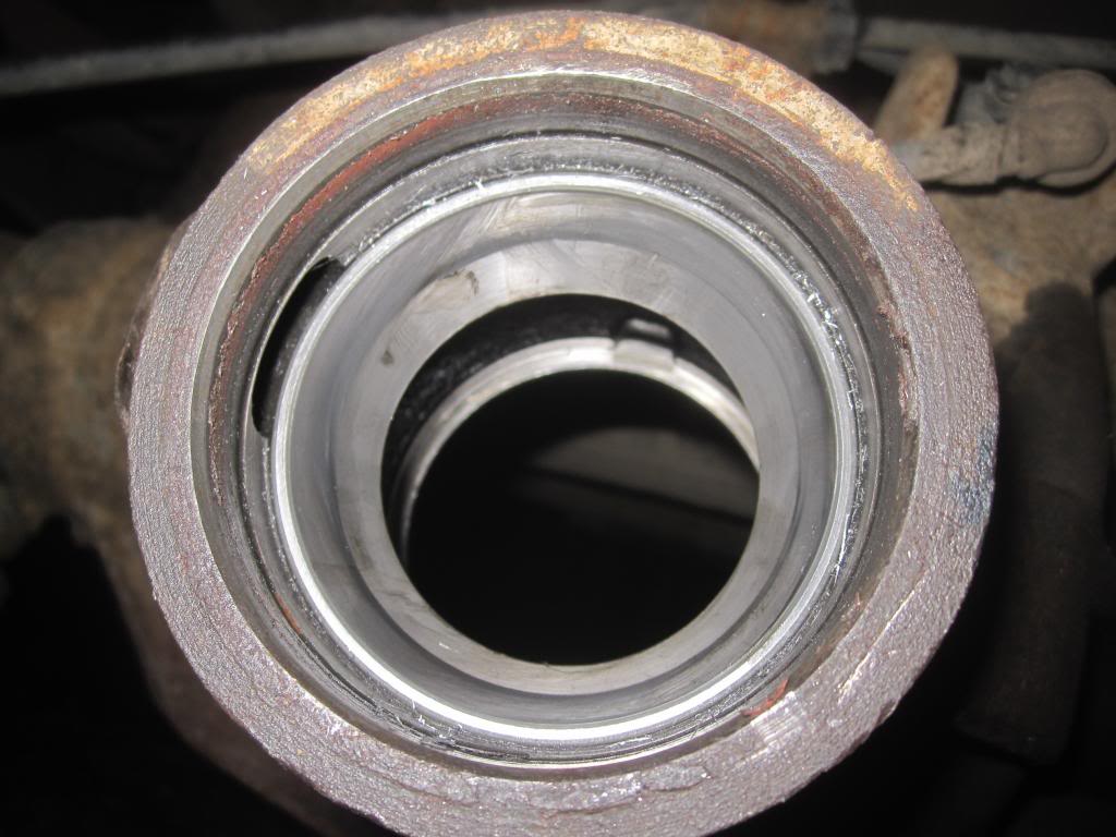
It will look like this when you’re done (notice the oil port on the left side).
All the metal shards are from the aluminum race installer. Now is a good time to spray the races with carb cleaner and wipe out the aluminum shavings.
In case you want to see what the old pinion races with 200k miles on them look like, here they are. Old on top, new on bottom. They actually looked pretty smooth.
...but a close up reveals surface irregularities:
Pinion Gear Crush Sleeve
Now you move to the pinion gear and its two bearings before you do anything else. The differential is still outside of the pumpkin and the axle shafts are still disconnected.
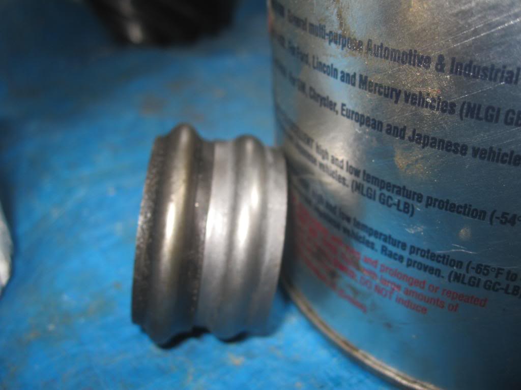
PUT THE NEW CRUSH SLEEVE ON THE PINION BEARING SHAFT. It will simply rest on the “shoulder” of the shaft. Here is a pic of old and new crush sleeve.
I don’t think it makes any difference which way it goes on.
Reinstall the Pinion Gear and Front Bearing
You pull the pinion gear in from the open side of the diff and if you’re alone like I was, you use a section of 2x4 or whatever you have on hand to lightly press against the pinion gear so it doesn’t slide out of the case while you’re working on the other side of the axle. It wants to fall out since it’s on an angle.
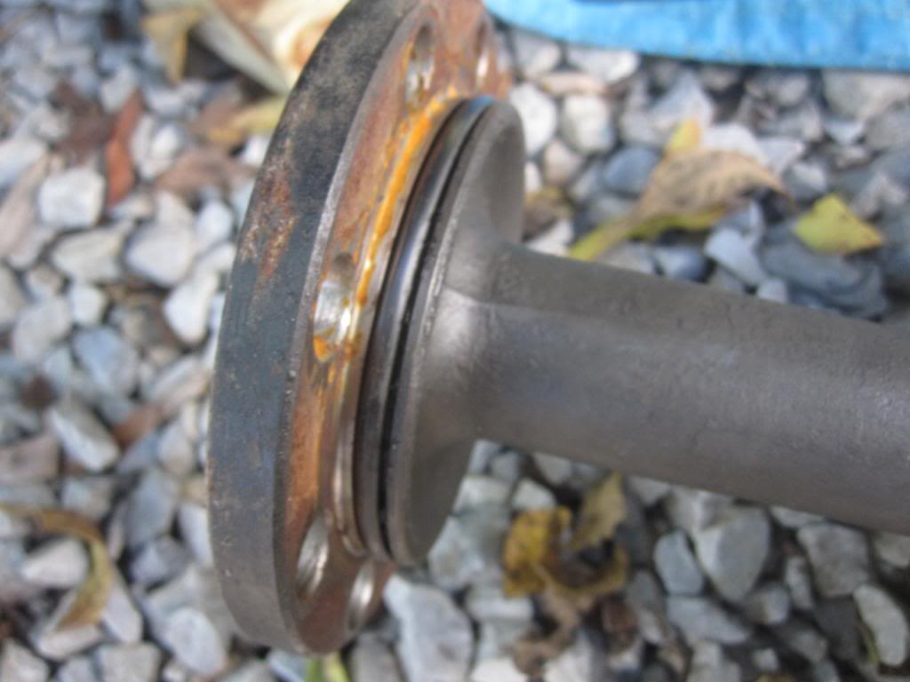
Then you put on the front bearing and the oil slinger you saved, with cylindrical bearings against the cup of course. Clean up that oil slinger with a rag before you stick it back on. Here it is:
Here is the front pinion bearing with the oil slinger on it and ready for the oil seal.
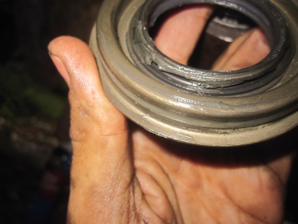
Install Pinion Oil Seal
Now you tap on the new pinion oil seal. This is easy. Just use a rubber mallet or a piece of plastic pipe and tap it on until it is seated. Don’t smash it and dent the metal face. Go easy.
You should lube the rubber parts with some gear oil before you put it on. Note that the oil seal has a tiny metal spring around the inside. DONT let that spring pop out or you can kiss that seal goodbye. I put a little gear lube on it to help keep it in place.
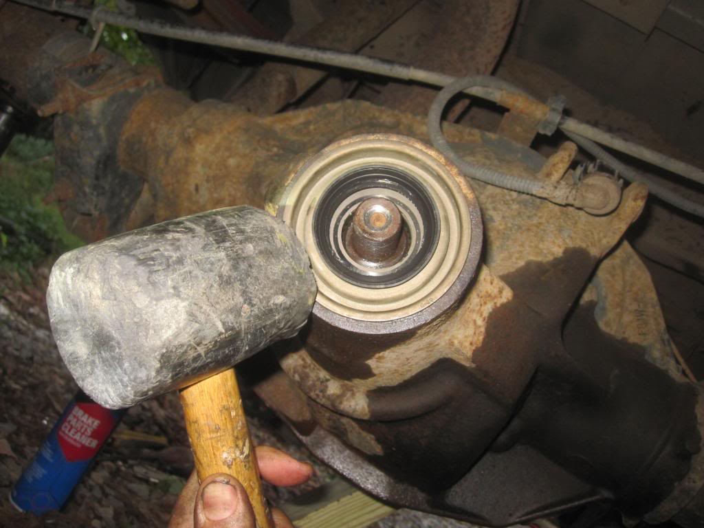
Now you put on the old plastic cover you saved:
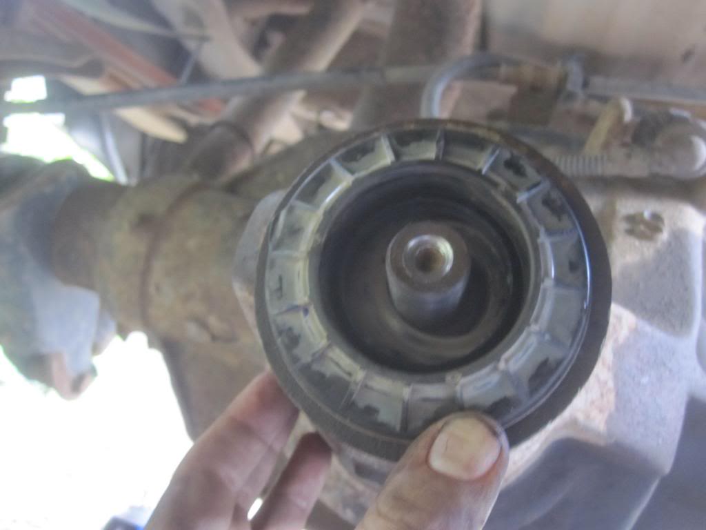
More in the next post....they won’t let me add more words in this post.
Now take a rag and wipe all the surfaces clean in preparation for the new races. This is some precision fit stuff. I got a little nervous when the front pinion race (this bearing and race come together as a unit in one box) didn’t have the exact same serial # etched into the back of it as the old race, but it fit. The accompanying paperwork indicated that it was for the 10.5.
You'll need a bearing/race installer kit. You can borrow one from Advance Auto or AutoZone or whomever. They aren’t expensive if you need to buy one. Maybe $40. They are made of aluminum so you don’t scratch the race surface as you smack it into place. You can use it with a sledge hammer or air chisel attachment. I used both. The sledge to start the new race into place, then the air chisel attachment to finish it.
Now just take the new race and push it into place by hand to get it started. It will stay in place.
Here is the race installer being placed over the new rear pinion race. Yes I know, the head of the tool is on backwards in this photo. It should go the other way.
Just seat it so it’s square and then start pounding. Smack the **** out of it. Just don’t hit anything in the differential case. Like I said above I used the air hammer/chisel after I had it in square, and it worked like a CHAMP. See here (I wasn’t sure if the tool was going to be too big...it just barely fit):
The manual says to take a feeler gauge to make sure you’ve pushed (seated) the new race all the way. I suggest you do so.
It’s pretty obvious when it’s seated. But smack it a few dozen extra times to be sure. That's what the mechanics at Ford told me they do.
Now take your 0.0015 of inch feeler gauge (a set are cheap at any auto parts store...$7) and make sure you seated the cups/races in all the way. If ya can’t jam it in between the back of the cups and the housing, you’re golden. If you can, you need to push the race in a tad more. Do this for both pinion races/cups.
Now time to install the front pinion race. Just push it in place to get it started, same as the other race:
And now use a smaller bearing installer tool to seat it.
This smaller race took me longer to get into place. It started going in a little too crooked for my taste so I chose to tap it out again with the brass drift and start again. Once I had it 1/4 way in using the sledge hammer I switched to the air hammer/chisel attachment and the little pucker just went right in. Just rotate the air hammer around as you use it and it will help it slide in faster. You want to hit different edges of the race in quick succession. I had to use the flat side of his bearing installer because the other side was slightly small…see how it’s on backwards?
It will look like this when you’re done (notice the oil port on the left side).
All the metal shards are from the aluminum race installer. Now is a good time to spray the races with carb cleaner and wipe out the aluminum shavings.
In case you want to see what the old pinion races with 200k miles on them look like, here they are. Old on top, new on bottom. They actually looked pretty smooth.
...but a close up reveals surface irregularities:
Pinion Gear Crush Sleeve
Now you move to the pinion gear and its two bearings before you do anything else. The differential is still outside of the pumpkin and the axle shafts are still disconnected.
PUT THE NEW CRUSH SLEEVE ON THE PINION BEARING SHAFT. It will simply rest on the “shoulder” of the shaft. Here is a pic of old and new crush sleeve.
I don’t think it makes any difference which way it goes on.
Reinstall the Pinion Gear and Front Bearing
You pull the pinion gear in from the open side of the diff and if you’re alone like I was, you use a section of 2x4 or whatever you have on hand to lightly press against the pinion gear so it doesn’t slide out of the case while you’re working on the other side of the axle. It wants to fall out since it’s on an angle.
Then you put on the front bearing and the oil slinger you saved, with cylindrical bearings against the cup of course. Clean up that oil slinger with a rag before you stick it back on. Here it is:
Here is the front pinion bearing with the oil slinger on it and ready for the oil seal.
Install Pinion Oil Seal
Now you tap on the new pinion oil seal. This is easy. Just use a rubber mallet or a piece of plastic pipe and tap it on until it is seated. Don’t smash it and dent the metal face. Go easy.
You should lube the rubber parts with some gear oil before you put it on. Note that the oil seal has a tiny metal spring around the inside. DONT let that spring pop out or you can kiss that seal goodbye. I put a little gear lube on it to help keep it in place.
Now you put on the old plastic cover you saved:
More in the next post....they won’t let me add more words in this post.
Last edited by Stewart_H; 11-21-2013 at 11:18 PM.
#4
09-22-2013, 09:20 PM
How to replace pinion bearings and carrier/side bearings in 10.5 inch rear differential
This is definitely DIFFERENTIALS FOR DUMMIES because I have never done anything like this before. But as Bill BillaVista says in his article, Gettin the Gears Done, “Yep, you sure can.”
His is an excellent article on the theory and tools needed. He is working on a DANA differential for the story but the theory is the same. Before you attempt this job, read his very well written article: http://www.pirate4x4.com/tech/billavista/Gear_Setup/. He is the expert, I am the newbie.
This article is nice as well, albeit for a Ford Mustang.
http://www.americanmuscle.com/differ...r-install.html
This one too:
http://www.autotechl.com/MATChapters...DiagRepair.pdf
Then read and look at my pics which provide more detail for the 10.5 and lots of pics and decide if you want to try to this yourself.
Below I will be replacing 2 pinion bearings (cone and cup or race) and 2 carrier or side bearings (cone and cup / race) in the 10.5 inch (Sterling / Visteon) rear differential of my 2002 F350 7.3l 4x4 automatic with Limited Slip Differential (some call it a “LOCKER”).
These instructions are in response to the following threads relating to loud whine in the rear end during acceleration from 20MPH to 50mph on my truck which has just under 200k miles on it.
A link to description of original symptom and PDF instructions from FORD for the Dana and Sterling/Visteon 10.5 are also included in these links:
https://www.ford-trucks.com/forums/1...l#post13251311
https://www.ford-trucks.com/forums/1...p-r-and-r.html
I don’t think this pumpkin has ever been worked on before aside from oil changes.
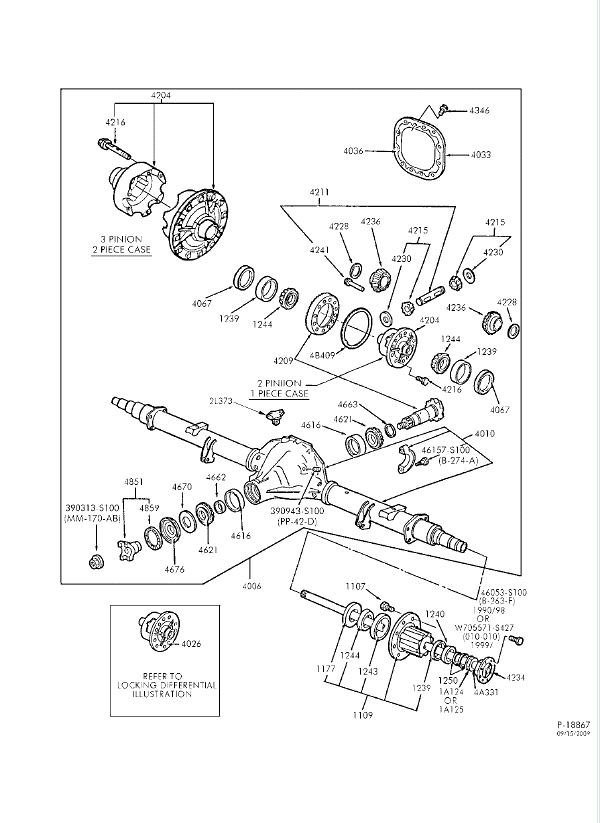
Parts explosion for the Ford Sterling 10.5 from the 7.3L diesel is here:
Tools Needed:
1. 2 Jack stands and something to chock your front tires so the truck cannot move forward once the rear tires are in the air.
2. Impact air or electrical tools are optional. If you don’t have them the job will be more tedious but still doable. They include
a. � impact gun (if not, a � inch drive ratchet)
b. 3/8 air ratchet (if not 1/2 inch drive ratchet with 3/8ths adapter)
c. Air hammer (optional)
3. � drive extension, at least 3 inches (to clear the ring gear when you are torqueing down the caps)
4. Pry bar or crow bar of at least 18 inches. If you have an assortment that’s even better.
5. 18 mm socket of any style
6. 1 and 1/8ths (or 28mm) deep, thin wall � inch drive socket (for pinion nut)
7. 13/16ths socket (for carrier bearing caps)
8. 2-3 foot section of pipe to use on your � ratchet or on your breaker bar for extra leverage if you have one. You’re going to need to exert 200-300 ft. pounds of force on the pinion nut.
9. Something to hold the end yoke while you squeeze down (tighten) the pinion nut. If you don’t have an impact gun, you will also need this when you remove the pinion nut. Your options include:
a. A large pipe wrench to go around the square part of the end yoke such as:
I did it this way and it worked fine for putting on the pinion nut. I used an impact gun to take the pinion nut off but this should work as well for getting the pinion nut off. OR
b. A chain strap wrench with a very long handle or in conjunction with a section of pipe to add some length for leverage, such as.
OR
c. Yoke Wrench:
OR
d. This cheaper version you bolt on with the 4 nuts from the yoke plus a breaker bar and section of pipe for added leverage:
10. Torque wrench(s) capable of between 20-90 foot pounds, clicker or beam style. Most important is the 80-90 ft. lb. range. You can do the rest by feel.
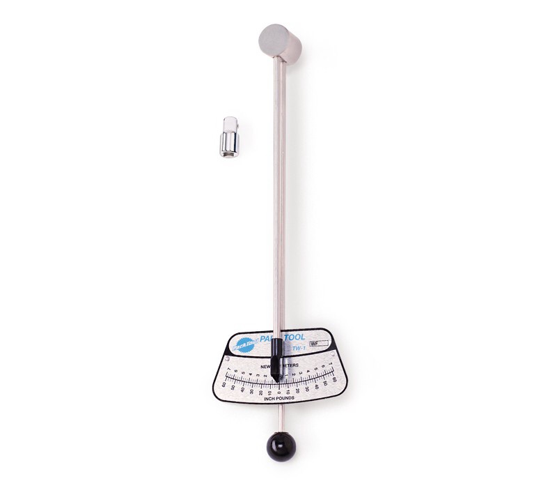
11. Beam type INCH POUND torque wrench that measures between 0-30 inch pounds. It must be small so it can spin around on the pinion nut without hitting the ground. Your options include:
a. Park Tool TW-1 Torque Wrench (1/4- Inch Drive, 0-60 inch Lbs) ($40) or something like this:
b. CDI Torque 1502LDIN 3/8-Inch Drive Memory Needle Dual Scale Torque Wrench, Torque Range 0 to 150-Inc ($150)
12. Dial indicator (to the thousands of an inch) and magnetic base (both are inexpensive)
13. Feeler gauge that includes a 0.0015 inch gauge.
14. 2 jaw large bearing puller (borrow from parts store or by online for $20). Not 3 jaw!
15. Bearing race and seal driver (borrow from parts store or buy online $40-60+)
16. Brass punch at least 8 inches long. (kinda optional…you could get away with using the handle on the bearing race driver, if it’s made of aluminum). A very hard piece of wood might work as well.
17. Rubber or wood mallet to tap the pinion oil seal in place.
18. 2-3 pound short handled sledge hammer and section of wood to smack the differential into place.
19. 8mm small box wrench for the 4 end yoke bolts. Ratcheting kind might not fit. 8mm socket and ratchet with swivel joint will also work.
20. 5-6 14oz spray cans of brake parts cleaner (Advance Auto sells them 2 for $5)
21. Gear marking paint like Permatex Prussian Blue (order online) and very small paint brush
22. Fine or medium point permanent marker
23. Metal marking punch to make permanent marks on hard metal parts. Could use a grease pen but…if the marks rub off…you’re in trouble. Could also use a cutting wheel on a die grinder to make a tiny mark.
24. Plenty of old rags
25. Oil pan
26. Local transmission shop to take off and press on 3 of the 4 bearings. ($30-40?)
27. 3.5 quarts 75-140 synthetic gear oil.
28. A small can of wheel bearing grease (synthetic preferably)
29. Permatex RTV black gasket maker or even better: Permatex 81182 Gear Oil RTV Gasket Maker, 3 oz. or equivalent by any other brand.
30. 1-2 6ml bottles of Loctite Blue medium threadlocker
31. Plastic baggies for nuts and bolts so you don’t lose them.
32. Clothes you can throw away after you’ve gotten them filthy with grease.
You may also need:
NOTE, I used air impact tools. You really will want to use an impact gun if only to get the pinion nut off with the wheels off the ground. But you can get away without it, as long you take the pinion nut off with the axle shafts still installed and the wheels on the ground, otherwise the pinion gear will just spin as you apply force to it. It’s nice to have the impact to use on the gear puller for the yoke as well, or you will be turning forever. BUT, it’s still doable with hand tools.
Other Considerations
I did this job alone, a pair of helping hands comes in handy but aren’t necessary. I also did this job with the entire rear end still on the truck. Many would take the entire rear end off of the truck because it’s easier to measure pinion preload when you can swing the small inch pound torque wrench 360 degrees, which you cannot do if the rear end is under the truck and because pulling the diff in and out is annoying as hell when in the seated position under the truck. For a bearings only replacement it’s ok to do this job with the rear end still on the truck.
If you have to pull out the differential over and over again to change the shims and modify backlash, I am forewarning you that your back will hurt from siting under the truck and prying the 100 pound diff in and out over and over. If you have a bad lower back, consider this a bad idea.
If you have a lift and can get the axle to eye level, then you’re better but you still won’t be able to rotate your torque wrench 360 degrees.
Parts:
If I had to do this overhaul over again I would have gotten an aftermarket master overhaul kit. The master kits from Yukon for example come with the 4 bearings (cones and cups), the oil seal, the crush sleeve, pinion nut and the gear marking paint and brush, and pinion and carrier shims in case you need to adjust backlash (not likely but possible) all for way cheaper than just the bearings cost from the “stealership”. Even wholesale prices at Ford suck compared to aftermarket. As an example, if you need shims from the dealership they will cost you $20 each. They charge $8 for a pinion nut at Ford. Absurd.
Here is an example of a complete aftermarket kit for less than $300 delivered:
If you do go to Ford, you will need:
� Both pinion bearing cones and cups (front/small and back/large)
� Both carrier bearing cones and cups (same parts for each side)
� Pinion nut
� Crush sleeve
� Pinion oil seal
� Friction modifier for the oil if the oil you are going to use doesn’t have any in it already
I’m not going to give you part #s because I don’t want you to get the wrong parts for your particular differential. Let the parts guys figure that out with your VIN #. Are they always the same for all 10.5 inch gears? I don’t know….
-----------------------------------------------------------------------------------------------------
His is an excellent article on the theory and tools needed. He is working on a DANA differential for the story but the theory is the same. Before you attempt this job, read his very well written article: http://www.pirate4x4.com/tech/billavista/Gear_Setup/. He is the expert, I am the newbie.
This article is nice as well, albeit for a Ford Mustang.
http://www.americanmuscle.com/differ...r-install.html
This one too:
http://www.autotechl.com/MATChapters...DiagRepair.pdf
Then read and look at my pics which provide more detail for the 10.5 and lots of pics and decide if you want to try to this yourself.
Below I will be replacing 2 pinion bearings (cone and cup or race) and 2 carrier or side bearings (cone and cup / race) in the 10.5 inch (Sterling / Visteon) rear differential of my 2002 F350 7.3l 4x4 automatic with Limited Slip Differential (some call it a “LOCKER”).
These instructions are in response to the following threads relating to loud whine in the rear end during acceleration from 20MPH to 50mph on my truck which has just under 200k miles on it.
A link to description of original symptom and PDF instructions from FORD for the Dana and Sterling/Visteon 10.5 are also included in these links:
https://www.ford-trucks.com/forums/1...l#post13251311
https://www.ford-trucks.com/forums/1...p-r-and-r.html
I don’t think this pumpkin has ever been worked on before aside from oil changes.
Parts explosion for the Ford Sterling 10.5 from the 7.3L diesel is here:
Tools Needed:
1. 2 Jack stands and something to chock your front tires so the truck cannot move forward once the rear tires are in the air.
2. Impact air or electrical tools are optional. If you don’t have them the job will be more tedious but still doable. They include
a. � impact gun (if not, a � inch drive ratchet)
b. 3/8 air ratchet (if not 1/2 inch drive ratchet with 3/8ths adapter)
c. Air hammer (optional)
3. � drive extension, at least 3 inches (to clear the ring gear when you are torqueing down the caps)
4. Pry bar or crow bar of at least 18 inches. If you have an assortment that’s even better.
5. 18 mm socket of any style
6. 1 and 1/8ths (or 28mm) deep, thin wall � inch drive socket (for pinion nut)
7. 13/16ths socket (for carrier bearing caps)
8. 2-3 foot section of pipe to use on your � ratchet or on your breaker bar for extra leverage if you have one. You’re going to need to exert 200-300 ft. pounds of force on the pinion nut.
9. Something to hold the end yoke while you squeeze down (tighten) the pinion nut. If you don’t have an impact gun, you will also need this when you remove the pinion nut. Your options include:
a. A large pipe wrench to go around the square part of the end yoke such as:
I did it this way and it worked fine for putting on the pinion nut. I used an impact gun to take the pinion nut off but this should work as well for getting the pinion nut off. OR
b. A chain strap wrench with a very long handle or in conjunction with a section of pipe to add some length for leverage, such as.
OR
c. Yoke Wrench:
OR
d. This cheaper version you bolt on with the 4 nuts from the yoke plus a breaker bar and section of pipe for added leverage:
10. Torque wrench(s) capable of between 20-90 foot pounds, clicker or beam style. Most important is the 80-90 ft. lb. range. You can do the rest by feel.
11. Beam type INCH POUND torque wrench that measures between 0-30 inch pounds. It must be small so it can spin around on the pinion nut without hitting the ground. Your options include:
a. Park Tool TW-1 Torque Wrench (1/4- Inch Drive, 0-60 inch Lbs) ($40) or something like this:
b. CDI Torque 1502LDIN 3/8-Inch Drive Memory Needle Dual Scale Torque Wrench, Torque Range 0 to 150-Inc ($150)
12. Dial indicator (to the thousands of an inch) and magnetic base (both are inexpensive)
13. Feeler gauge that includes a 0.0015 inch gauge.
14. 2 jaw large bearing puller (borrow from parts store or by online for $20). Not 3 jaw!
15. Bearing race and seal driver (borrow from parts store or buy online $40-60+)
16. Brass punch at least 8 inches long. (kinda optional…you could get away with using the handle on the bearing race driver, if it’s made of aluminum). A very hard piece of wood might work as well.
17. Rubber or wood mallet to tap the pinion oil seal in place.
18. 2-3 pound short handled sledge hammer and section of wood to smack the differential into place.
19. 8mm small box wrench for the 4 end yoke bolts. Ratcheting kind might not fit. 8mm socket and ratchet with swivel joint will also work.
20. 5-6 14oz spray cans of brake parts cleaner (Advance Auto sells them 2 for $5)
21. Gear marking paint like Permatex Prussian Blue (order online) and very small paint brush
22. Fine or medium point permanent marker
23. Metal marking punch to make permanent marks on hard metal parts. Could use a grease pen but…if the marks rub off…you’re in trouble. Could also use a cutting wheel on a die grinder to make a tiny mark.
24. Plenty of old rags
25. Oil pan
26. Local transmission shop to take off and press on 3 of the 4 bearings. ($30-40?)
27. 3.5 quarts 75-140 synthetic gear oil.
28. A small can of wheel bearing grease (synthetic preferably)
29. Permatex RTV black gasket maker or even better: Permatex 81182 Gear Oil RTV Gasket Maker, 3 oz. or equivalent by any other brand.
30. 1-2 6ml bottles of Loctite Blue medium threadlocker
31. Plastic baggies for nuts and bolts so you don’t lose them.
32. Clothes you can throw away after you’ve gotten them filthy with grease.
You may also need:
- Calipers (digital preferably) that measure thousands of an inch
NOTE, I used air impact tools. You really will want to use an impact gun if only to get the pinion nut off with the wheels off the ground. But you can get away without it, as long you take the pinion nut off with the axle shafts still installed and the wheels on the ground, otherwise the pinion gear will just spin as you apply force to it. It’s nice to have the impact to use on the gear puller for the yoke as well, or you will be turning forever. BUT, it’s still doable with hand tools.
Other Considerations
I did this job alone, a pair of helping hands comes in handy but aren’t necessary. I also did this job with the entire rear end still on the truck. Many would take the entire rear end off of the truck because it’s easier to measure pinion preload when you can swing the small inch pound torque wrench 360 degrees, which you cannot do if the rear end is under the truck and because pulling the diff in and out is annoying as hell when in the seated position under the truck. For a bearings only replacement it’s ok to do this job with the rear end still on the truck.
If you have to pull out the differential over and over again to change the shims and modify backlash, I am forewarning you that your back will hurt from siting under the truck and prying the 100 pound diff in and out over and over. If you have a bad lower back, consider this a bad idea.
If you have a lift and can get the axle to eye level, then you’re better but you still won’t be able to rotate your torque wrench 360 degrees.
Parts:
If I had to do this overhaul over again I would have gotten an aftermarket master overhaul kit. The master kits from Yukon for example come with the 4 bearings (cones and cups), the oil seal, the crush sleeve, pinion nut and the gear marking paint and brush, and pinion and carrier shims in case you need to adjust backlash (not likely but possible) all for way cheaper than just the bearings cost from the “stealership”. Even wholesale prices at Ford suck compared to aftermarket. As an example, if you need shims from the dealership they will cost you $20 each. They charge $8 for a pinion nut at Ford. Absurd.
Here is an example of a complete aftermarket kit for less than $300 delivered:
If you do go to Ford, you will need:
� Both pinion bearing cones and cups (front/small and back/large)
� Both carrier bearing cones and cups (same parts for each side)
� Pinion nut
� Crush sleeve
� Pinion oil seal
� Friction modifier for the oil if the oil you are going to use doesn’t have any in it already
I’m not going to give you part #s because I don’t want you to get the wrong parts for your particular differential. Let the parts guys figure that out with your VIN #. Are they always the same for all 10.5 inch gears? I don’t know….
-----------------------------------------------------------------------------------------------------
Last edited by Stewart_H; 11-22-2013 at 07:14 PM.
#5
09-22-2013, 09:20 PM
How to replace pinion bearings and carrier/side bearings in 10.5 inch rear differential
Let’s get started:
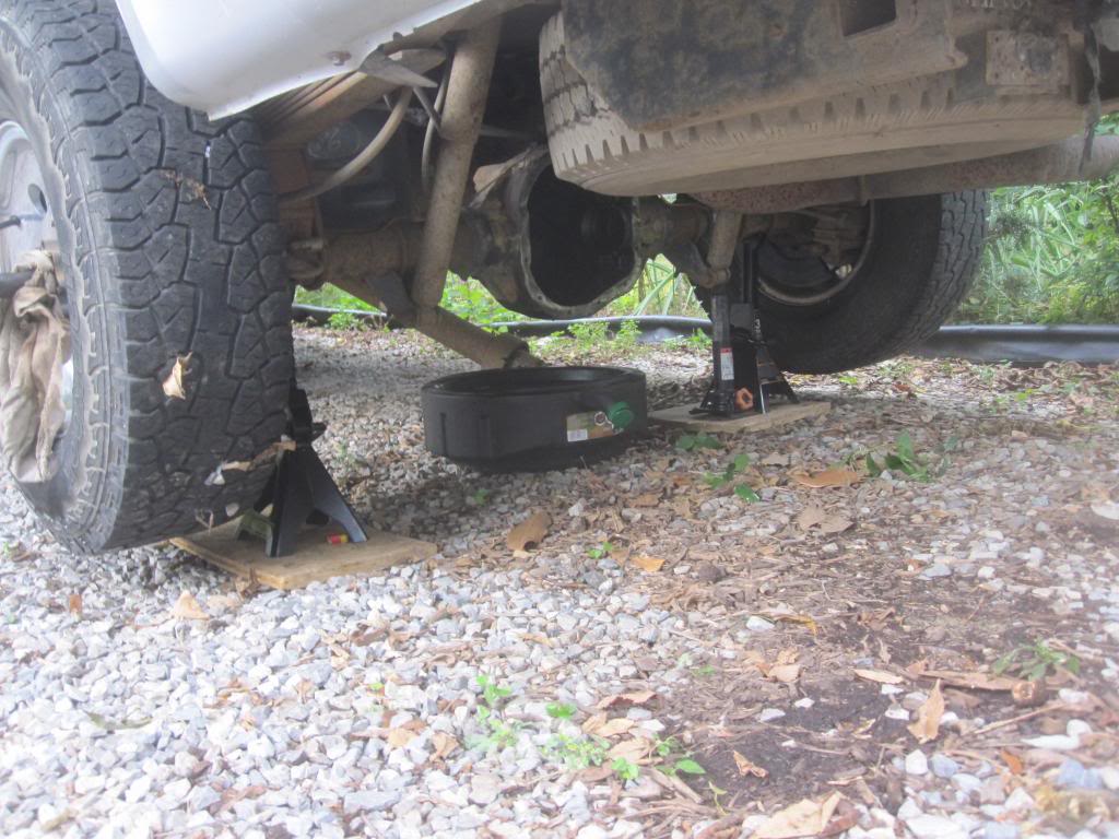
Raise the Truck
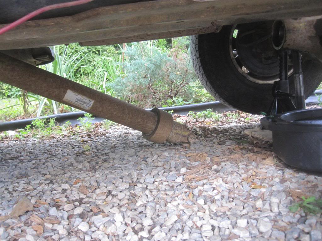
I put the rear axle on jack stands to make more room for myself. You don’t have to. It can be in the ground, but you won’t be happy about that decision. Needless to say, you don’t need to take the wheels off. Drop the spare tire as well to have more space to sit up under the truck.
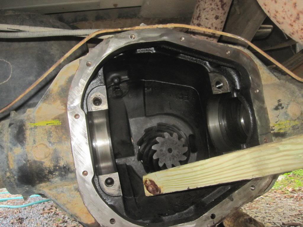
Remove Cover, Inspect Gears
My first steps after removing the cover bolts (12mm?) and prying the cover off was to inspect the gears visually for excessive wear or non-repairable damage. Don’t bother changing the bearings if the gears are in bad shape. Plenty of articles exist online on what to look for. Basically all the gear teeth need to look smooth, not chipped or worn to a point. If you’re not sure, upload some pics for us to look at.
Check Backlash
After sharing some pictures of my gears with and getting the ok to proceed from a Ford truck mechanic, I wanted to check backlash on the gears as I found them in the case to help diagnose the cause of my issue. I found a few videos on YouTube which demonstrate how to do this. It requires you to partially remove (disengage) the axle shafts and disconnect the drive shaft from the end yoke. Pics of that removal are shown below.
Now that you have the driveline disconnected and the axe shafts disengaged from the differential you can check the backlash and runout. Truth be told...the Ford mechanic I spoke to says they NEVER check backlash or runout when they change pinion and differential carrier bearings. They just R&R (remove and replace) as long as the gears are smooth. But I was curious because the rear end was making so much noise and since I have a dial indicator and magnetic base I figured I would try it out.
I used this fine gentleman's video showing how to measure backlash. Note that you don’t really need to hold the end yoke with your hand to keep it from spinning while you check the backlash. But do so until you get the hang of it.
Here are the pics of my dial indicator and how I placed it on the gears to make the backlash measurement. You’re simply looking for how close the pinion and ring gear are to one another.
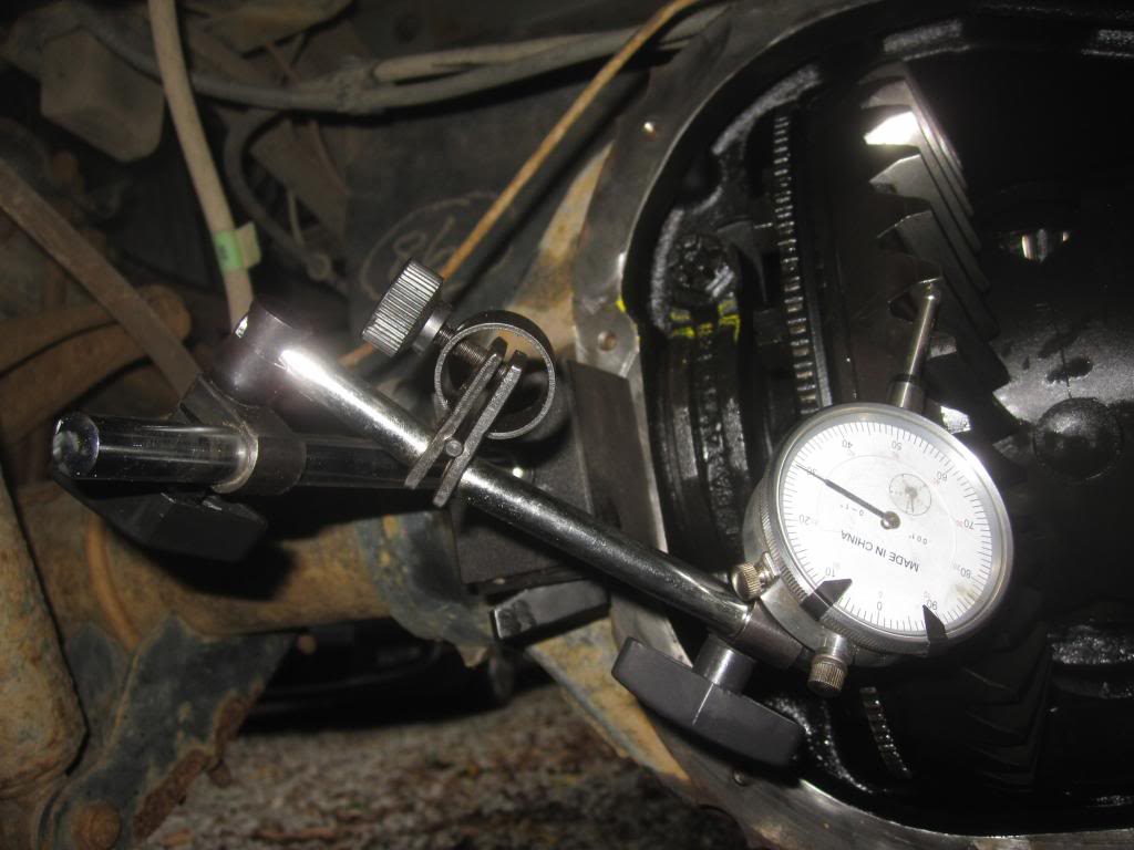
And a close up of the exact placement of the indicator. I had an average of 20 thousands of backlash (too much). The manual calls for Max Backlash Between Ring Gear and Pinion Teeth of 0.008-0.015, or 8-15 thousands of an inch, and more preferably 12-15 thousands. This is a CRITICAL measurement which you must do on multiple teeth…at least 4 teeth.
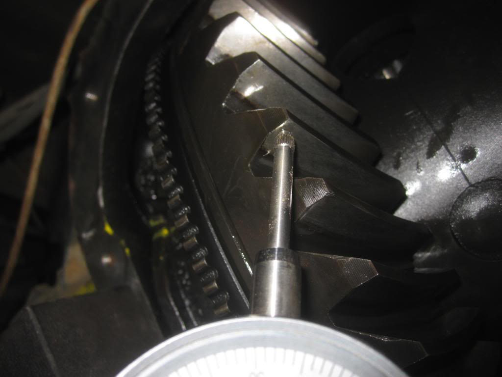
Then I attempted to measure Maximum Back Face Ring Gear Runout. Problem is I wasn’t actually sure from the diagram in the manual where I was supposed to measure. So I tried here:
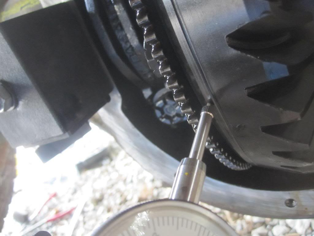
In this case I believe you need to spin the gear a complete revolution to get the total ring gear +deviation. Anyway mine had less than 5 thousands total deviation. The Ford manual calls for "0.004" inches deviation. But don’t trust me on this one. Either way this doesn’t appear to be a critical measurement, so don’t worry about it.
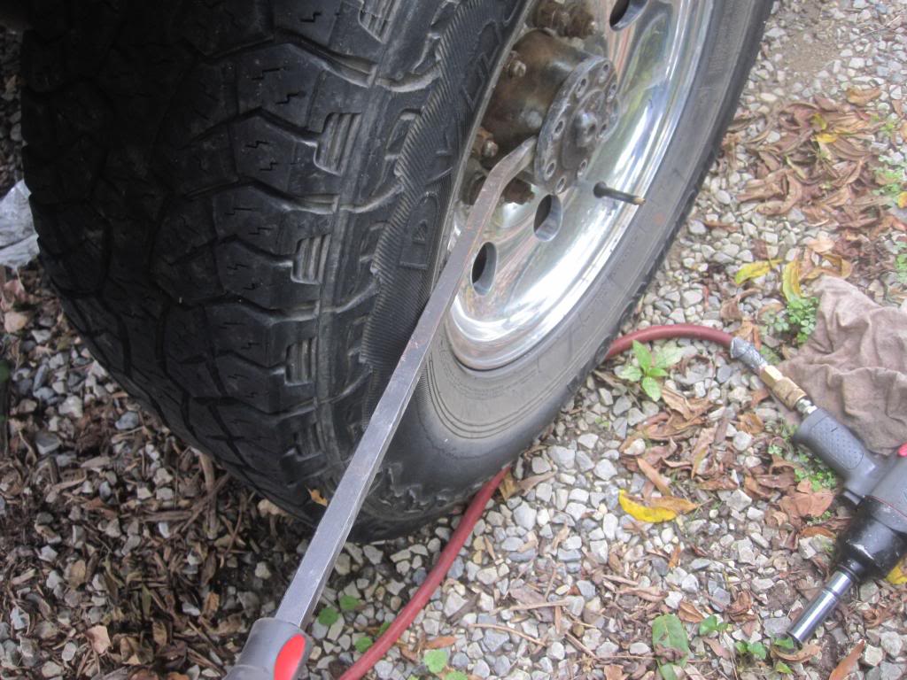
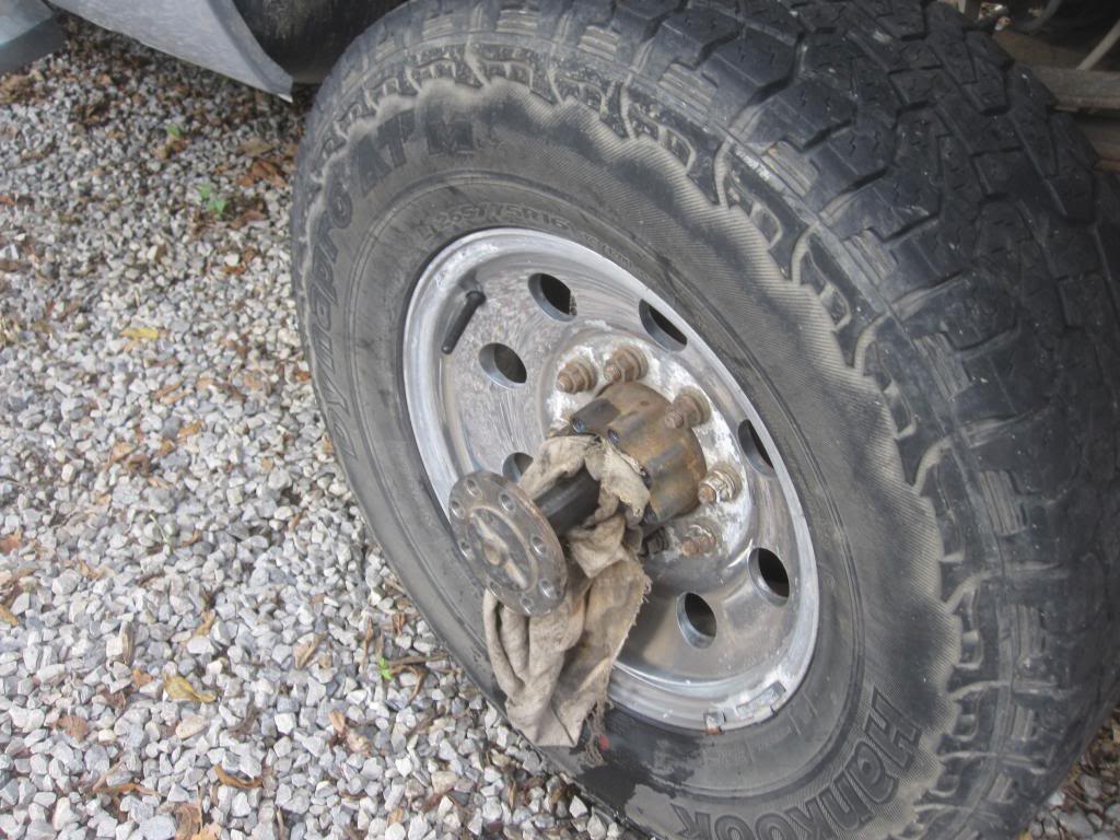
Remove Axle Shafts
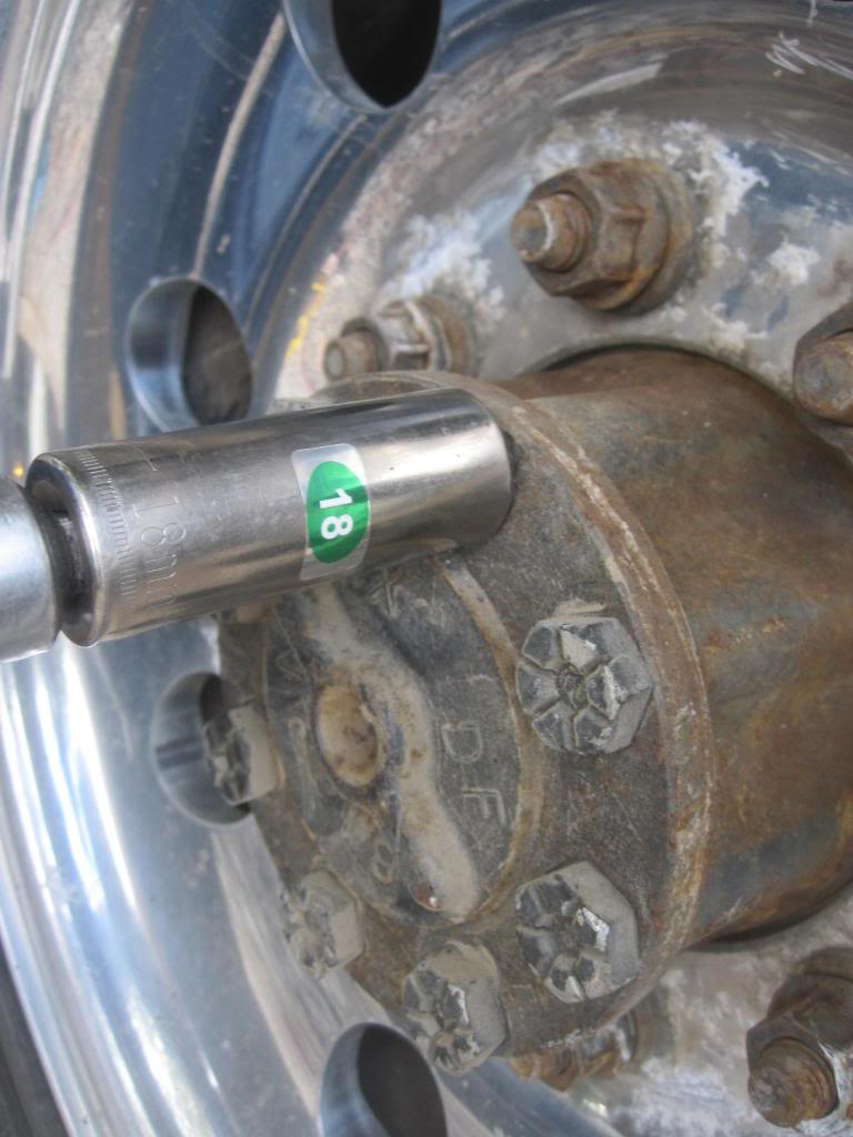
Step 1 after inspecting your gears, is to pull out the axles (18mm socket) and then use a crow bar or pry bar to pop them free. Oil will run out so have some rags handy to jam in there. Just pull them out far enough to clear the differential. You’ll know they are out of the differential because the axle shafts will spin freely.
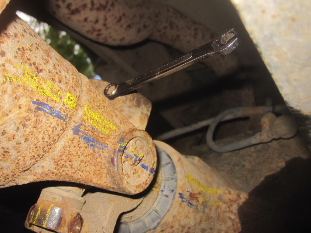
Disconnect Driveshaft
Now mark the driveline and yoke because you need put them back together in the same orientation. I used a grease pen but honestly it’s not a good idea because you will end up rubbing the markings off the end yoke from handling it so much.
Then remove the four 8mm bolts holding the yoke together. You must use a closed wrench not an open wrench. An open wrench won’t be strong enough and will deform and you will strip the bolt....don’t ask me how I know. Impact ratchet will only work if the 4 bolts are accessible which depends on what position the drive shaft has rested in when you came to a stop.
See:
Then remove the 2 small brackets held in place by the four 8mm bolts and smack the yoke with a rubber mallet to separate the driveline and push that thang out of the way.
Raise the Truck
I put the rear axle on jack stands to make more room for myself. You don’t have to. It can be in the ground, but you won’t be happy about that decision. Needless to say, you don’t need to take the wheels off. Drop the spare tire as well to have more space to sit up under the truck.
Remove Cover, Inspect Gears
My first steps after removing the cover bolts (12mm?) and prying the cover off was to inspect the gears visually for excessive wear or non-repairable damage. Don’t bother changing the bearings if the gears are in bad shape. Plenty of articles exist online on what to look for. Basically all the gear teeth need to look smooth, not chipped or worn to a point. If you’re not sure, upload some pics for us to look at.
Check Backlash
After sharing some pictures of my gears with and getting the ok to proceed from a Ford truck mechanic, I wanted to check backlash on the gears as I found them in the case to help diagnose the cause of my issue. I found a few videos on YouTube which demonstrate how to do this. It requires you to partially remove (disengage) the axle shafts and disconnect the drive shaft from the end yoke. Pics of that removal are shown below.
Now that you have the driveline disconnected and the axe shafts disengaged from the differential you can check the backlash and runout. Truth be told...the Ford mechanic I spoke to says they NEVER check backlash or runout when they change pinion and differential carrier bearings. They just R&R (remove and replace) as long as the gears are smooth. But I was curious because the rear end was making so much noise and since I have a dial indicator and magnetic base I figured I would try it out.
I used this fine gentleman's video showing how to measure backlash. Note that you don’t really need to hold the end yoke with your hand to keep it from spinning while you check the backlash. But do so until you get the hang of it.
Here are the pics of my dial indicator and how I placed it on the gears to make the backlash measurement. You’re simply looking for how close the pinion and ring gear are to one another.
And a close up of the exact placement of the indicator. I had an average of 20 thousands of backlash (too much). The manual calls for Max Backlash Between Ring Gear and Pinion Teeth of 0.008-0.015, or 8-15 thousands of an inch, and more preferably 12-15 thousands. This is a CRITICAL measurement which you must do on multiple teeth…at least 4 teeth.
Then I attempted to measure Maximum Back Face Ring Gear Runout. Problem is I wasn’t actually sure from the diagram in the manual where I was supposed to measure. So I tried here:
In this case I believe you need to spin the gear a complete revolution to get the total ring gear +deviation. Anyway mine had less than 5 thousands total deviation. The Ford manual calls for "0.004" inches deviation. But don’t trust me on this one. Either way this doesn’t appear to be a critical measurement, so don’t worry about it.
Remove Axle Shafts
Step 1 after inspecting your gears, is to pull out the axles (18mm socket) and then use a crow bar or pry bar to pop them free. Oil will run out so have some rags handy to jam in there. Just pull them out far enough to clear the differential. You’ll know they are out of the differential because the axle shafts will spin freely.
Disconnect Driveshaft
Now mark the driveline and yoke because you need put them back together in the same orientation. I used a grease pen but honestly it’s not a good idea because you will end up rubbing the markings off the end yoke from handling it so much.
Then remove the four 8mm bolts holding the yoke together. You must use a closed wrench not an open wrench. An open wrench won’t be strong enough and will deform and you will strip the bolt....don’t ask me how I know. Impact ratchet will only work if the 4 bolts are accessible which depends on what position the drive shaft has rested in when you came to a stop.
See:
Then remove the 2 small brackets held in place by the four 8mm bolts and smack the yoke with a rubber mallet to separate the driveline and push that thang out of the way.
Last edited by Stewart_H; 11-21-2013 at 11:06 PM.
#6
09-22-2013, 09:20 PM
How to replace pinion bearings and carrier/side bearings in 10.5 inch rear differential
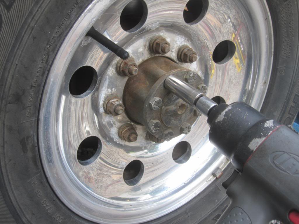
Remove the Pinion Nut
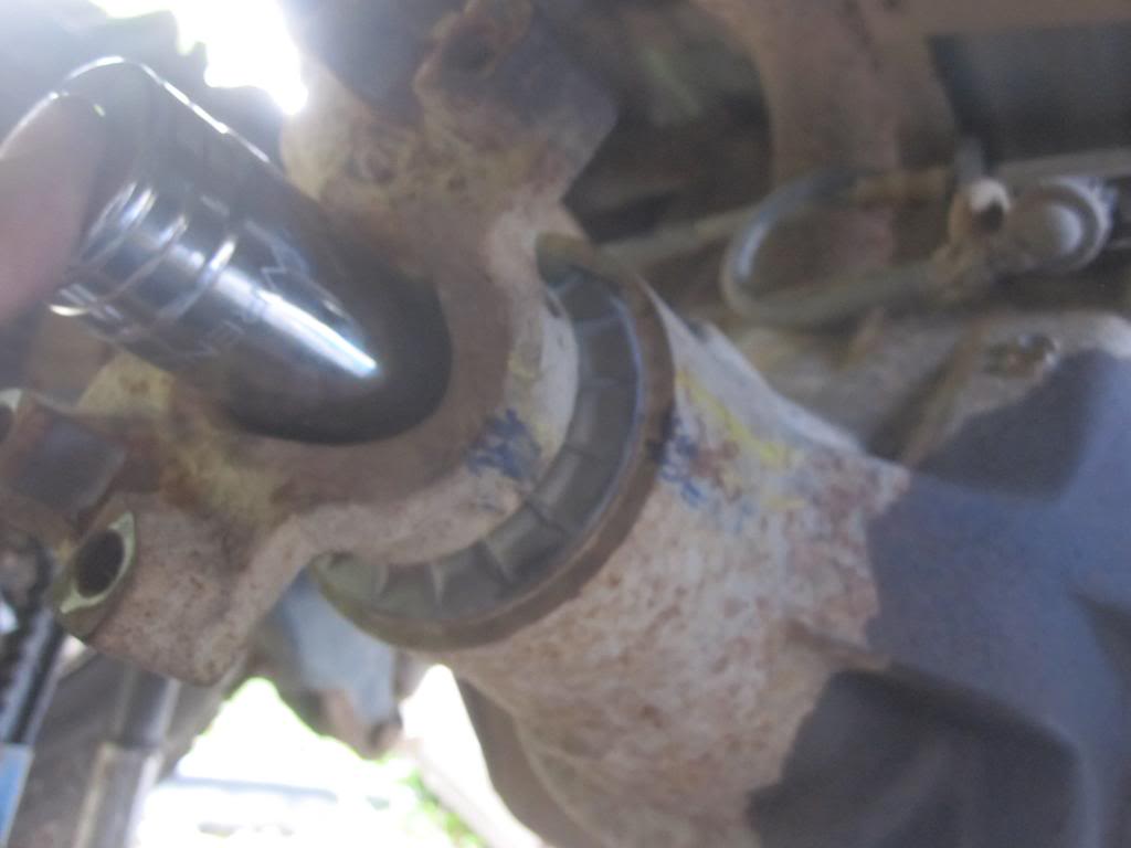
Now, you want to prepare to take the pinion nut off (which according to the Ford mechanic I know, they always reuse even though the manual explicitly tells you not to). Clean the dirt away from around the nut which is 1 1/8 inch or 28 mm. 12 point or 6 point socket will work. I used a 12 point because it’s all I had handy. It came off quite easily with my impact gun. I only needed to hold the yoke with my hand to keep it from spinning.
If you don’t have an impact gun, my list of tools above gives you alternatives on how to hold the end yoke still while you take off the pinion nut.
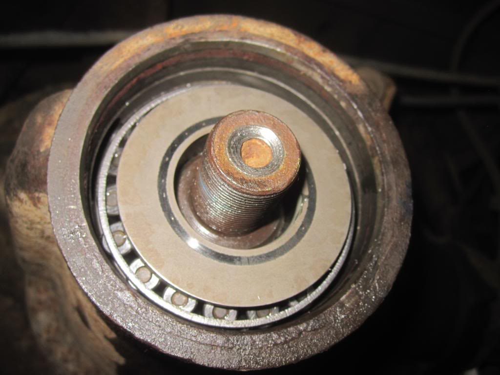
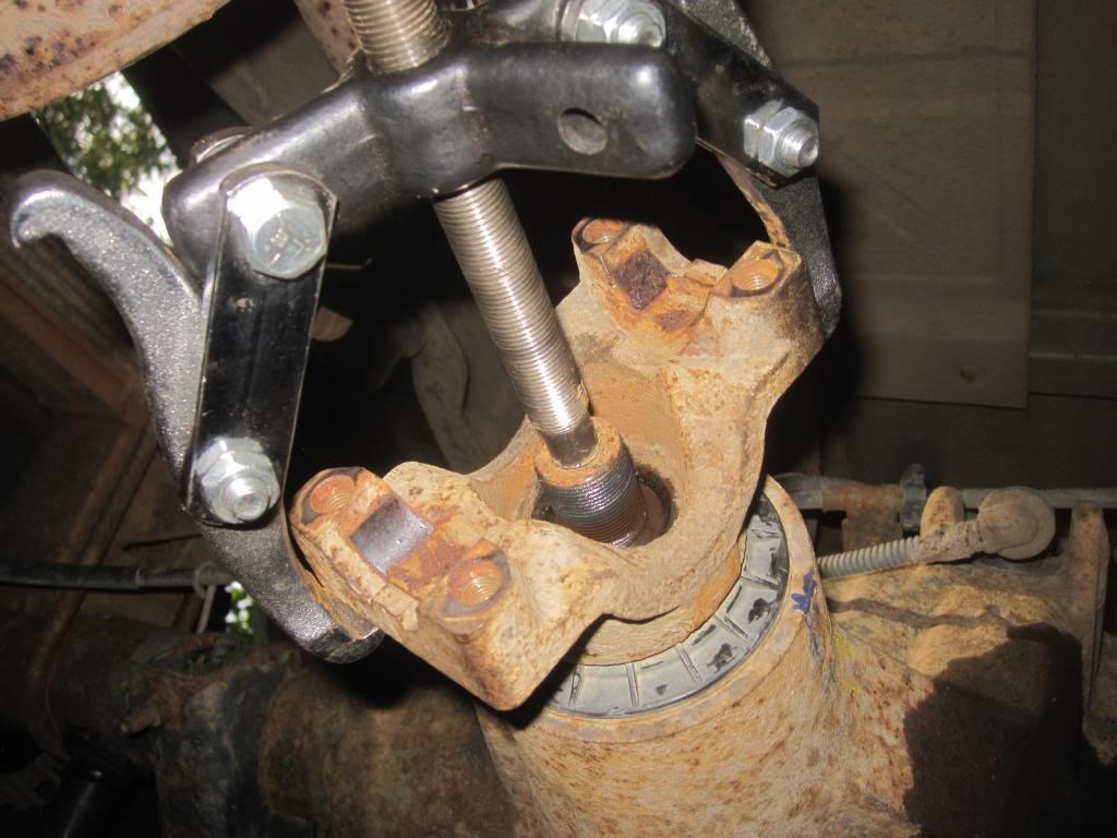
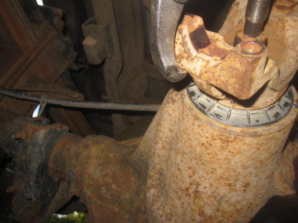
Remove End Yoke with Gear Puller
Now you use a 2 jaw bearing puller (which you can buy anywhere for cheap or borrow from Advance Auto) to pull the end yoke off of the end of the pinion shaft.
You actually put the hooked jaws on the side of the yoke and not the base, otherwise it will constantly slip off. See my pics.
The yoke has a long way to come off...so you will need to spin the gear puller for a while. But it’s easy enough. I had long and short jaws in the set I borrowed. The short jaws were better for this job because you’re hooking into the "arms" of the yoke and not the bottom of it.
Remove and Discard Pinion Oil Seal
Now you pry the old oil seal off. I tried a seal puller but it wasn’t strong enough, so I just used a flat head screw driver and a hammer and got under the lip of the lil SOB and pried it up and out. Yes some oil will drip out so have an oil pan handy. The oil seal will be replaced so you can destroy it as you take it off. If its relatively new and you want to reuse it…take it off carefully with a small screwdriver….prying it off all around. It can be done.
Remove Front Pinion Bearing Cone
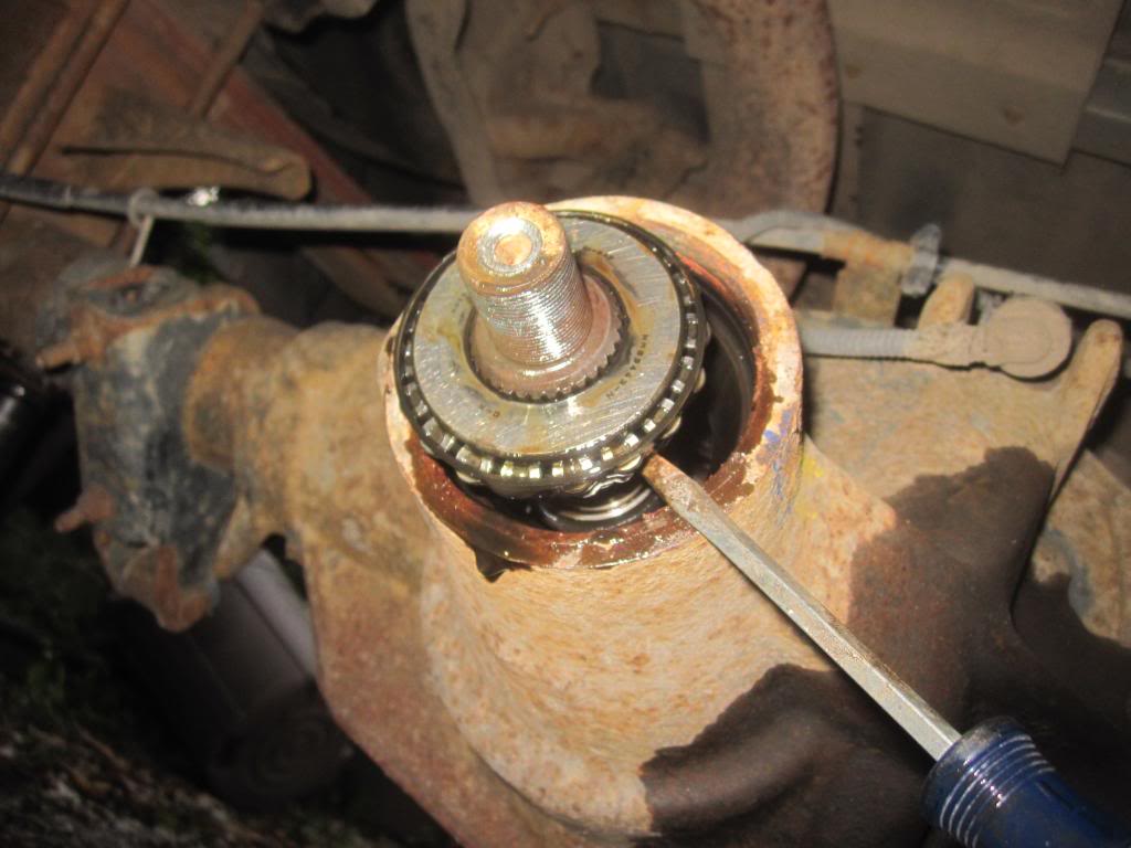
Underneath the oil seal you will find a very thin metal "washer" or oil slinger. LABEL IT with your sharpie, Keep it and reuse it. See here:
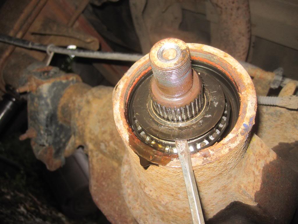
Now you pull the front pinion bearing out with a screw driver. It will be easily to simple pull out with your fingers or a screw driver.
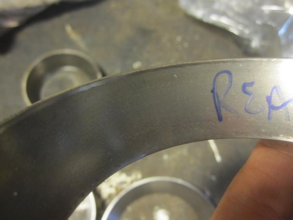
Mark and Remove the Carrier Bearing Caps
Now it’s time to get back to the other side of the differential and mark the "brackets" or CAPS which hold the side carrier bearing races/cups and spacers in place.
It is CRITICAL that you mark which way these go (up down and side to side orientation) because they are unique to the differential and not replaceable.
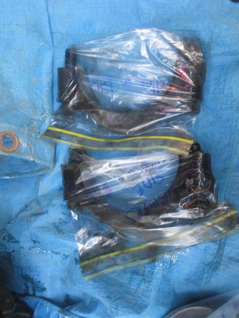
I used markers, grease pen, and even scratched the surface. Then I put them in plastic baggies and wrote on the bag as well to be sure I know which goes where and which end is up.
And now the other side.
You then use a 13/16ths socket and your impact gun and remove the 4 bolts that hold in the 2 brackets. See the socket on the bolt I refer to? They came off very easily.
Now, you want to prepare to take the pinion nut off (which according to the Ford mechanic I know, they always reuse even though the manual explicitly tells you not to). Clean the dirt away from around the nut which is 1 1/8 inch or 28 mm. 12 point or 6 point socket will work. I used a 12 point because it’s all I had handy. It came off quite easily with my impact gun. I only needed to hold the yoke with my hand to keep it from spinning.
If you don’t have an impact gun, my list of tools above gives you alternatives on how to hold the end yoke still while you take off the pinion nut.
Remove End Yoke with Gear Puller
Now you use a 2 jaw bearing puller (which you can buy anywhere for cheap or borrow from Advance Auto) to pull the end yoke off of the end of the pinion shaft.
You actually put the hooked jaws on the side of the yoke and not the base, otherwise it will constantly slip off. See my pics.
The yoke has a long way to come off...so you will need to spin the gear puller for a while. But it’s easy enough. I had long and short jaws in the set I borrowed. The short jaws were better for this job because you’re hooking into the "arms" of the yoke and not the bottom of it.
Remove and Discard Pinion Oil Seal
Now you pry the old oil seal off. I tried a seal puller but it wasn’t strong enough, so I just used a flat head screw driver and a hammer and got under the lip of the lil SOB and pried it up and out. Yes some oil will drip out so have an oil pan handy. The oil seal will be replaced so you can destroy it as you take it off. If its relatively new and you want to reuse it…take it off carefully with a small screwdriver….prying it off all around. It can be done.
Remove Front Pinion Bearing Cone
Underneath the oil seal you will find a very thin metal "washer" or oil slinger. LABEL IT with your sharpie, Keep it and reuse it. See here:
Now you pull the front pinion bearing out with a screw driver. It will be easily to simple pull out with your fingers or a screw driver.
Mark and Remove the Carrier Bearing Caps
Now it’s time to get back to the other side of the differential and mark the "brackets" or CAPS which hold the side carrier bearing races/cups and spacers in place.
It is CRITICAL that you mark which way these go (up down and side to side orientation) because they are unique to the differential and not replaceable.
I used markers, grease pen, and even scratched the surface. Then I put them in plastic baggies and wrote on the bag as well to be sure I know which goes where and which end is up.
And now the other side.
You then use a 13/16ths socket and your impact gun and remove the 4 bolts that hold in the 2 brackets. See the socket on the bolt I refer to? They came off very easily.
Last edited by Stewart_H; 11-21-2013 at 11:07 PM.
#7
09-22-2013, 09:20 PM
How to replace pinion bearings and carrier/side bearings in 10.5 inch rear differential
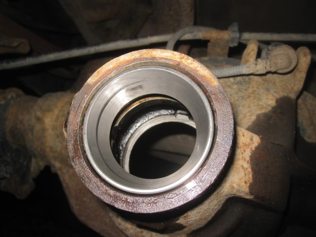
Once you have the bolts out you need to pry the differential with a pry bar or crow bar. (I don’t have any pics of that…sorry) Don’t damage the teeth. Use anything you can hook onto on the differential itself and pry it out, little by little, side to side. Put a bucket or something underneath to help catch the diff when it comes out. You don’t want it hitting the hard ground and chipping a gear tooth. Mine practically fell out because I had “spun cups” (more about that below).
It’s heavy!
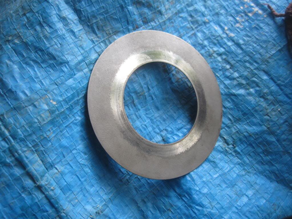
Be very careful to make sure the spacers located underneath the caps (they look like large metal washers) don’t fall out when you’re prying out the diff. Pay attention as to which spacer is on which side, label it and put it in a baggie. You will reuse the spacer with the new bearings. Note its orientation under the bracket as well. One or both sides of the shims will have a shaved corner to make installation easier. The shaved corner does towards the outside.
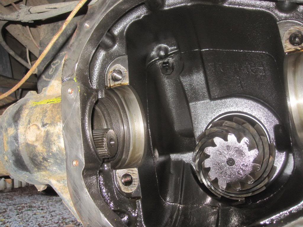
Then you have a mostly empty pumpkin with the exception of the pinion gear which just pulls right though because nothing is holding it place any longer. Ya see the end of the axle which you partially removed earlier sticking through on left side of pic?
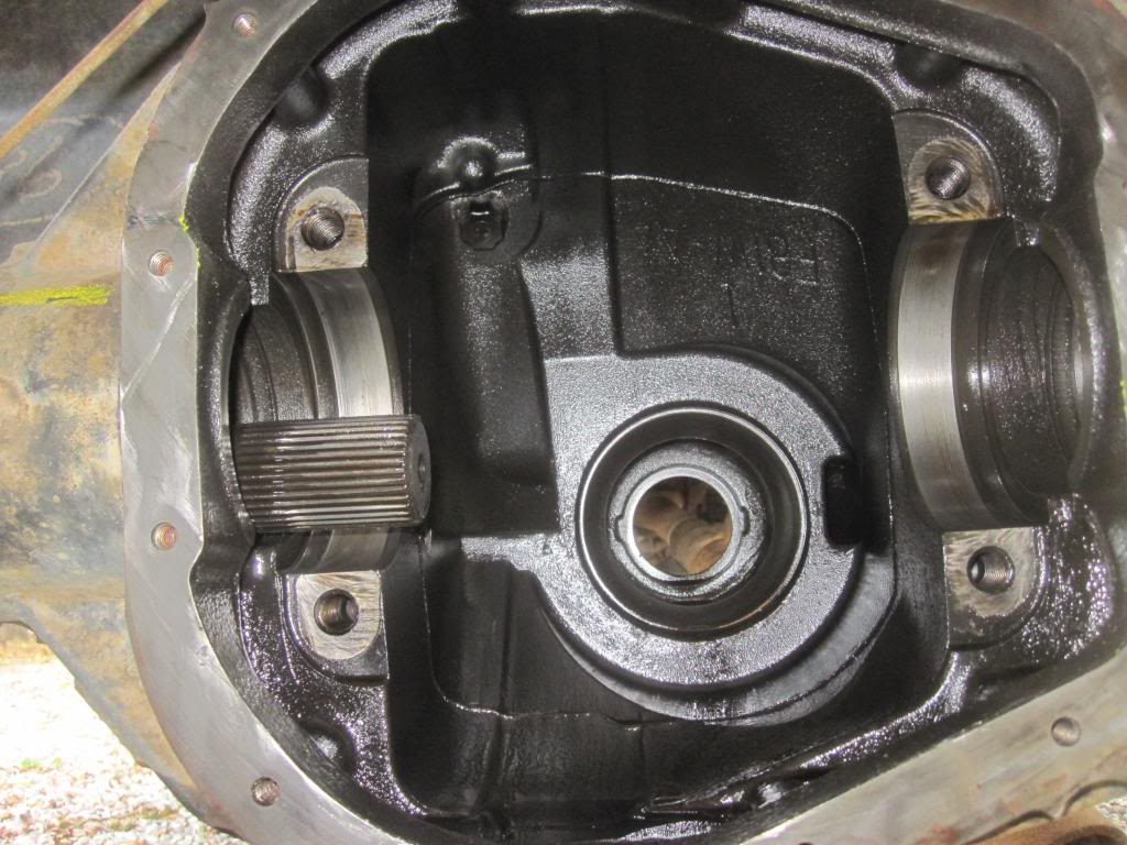
And the pumpkin without the pinion gear in it (you can see right through that sucka):
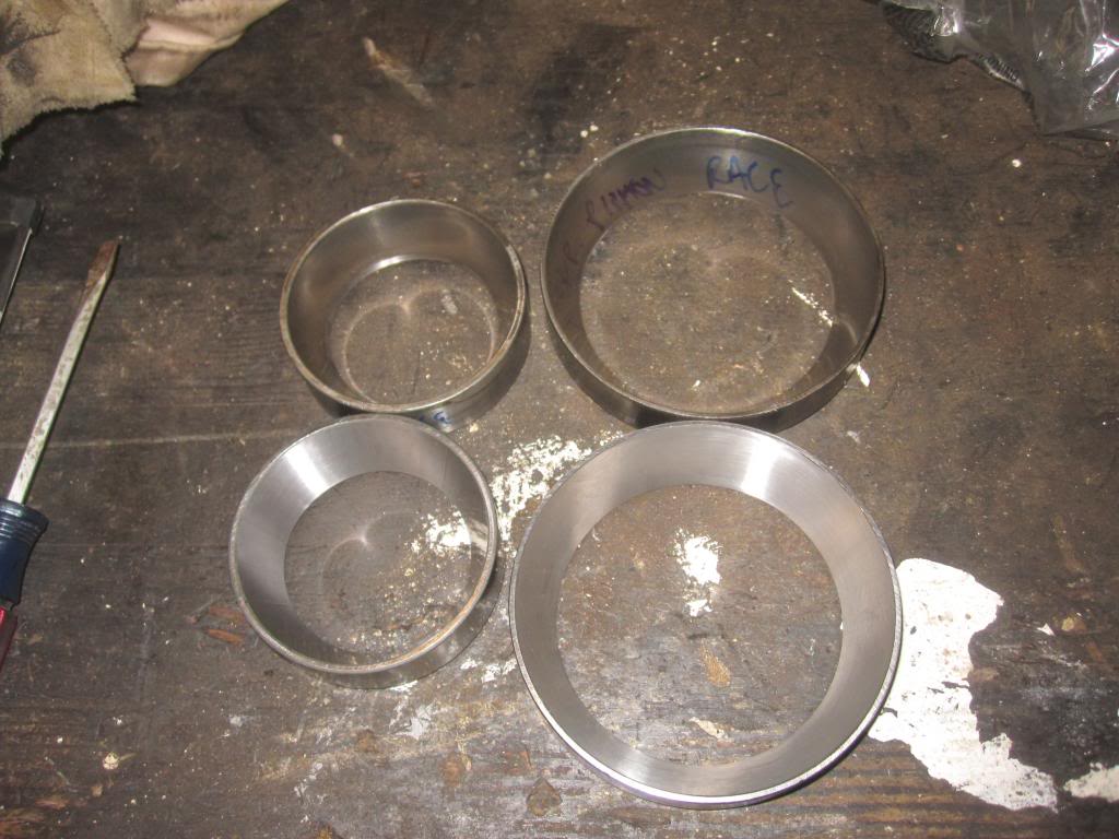
The caps look like this once out of the "pumpkin":
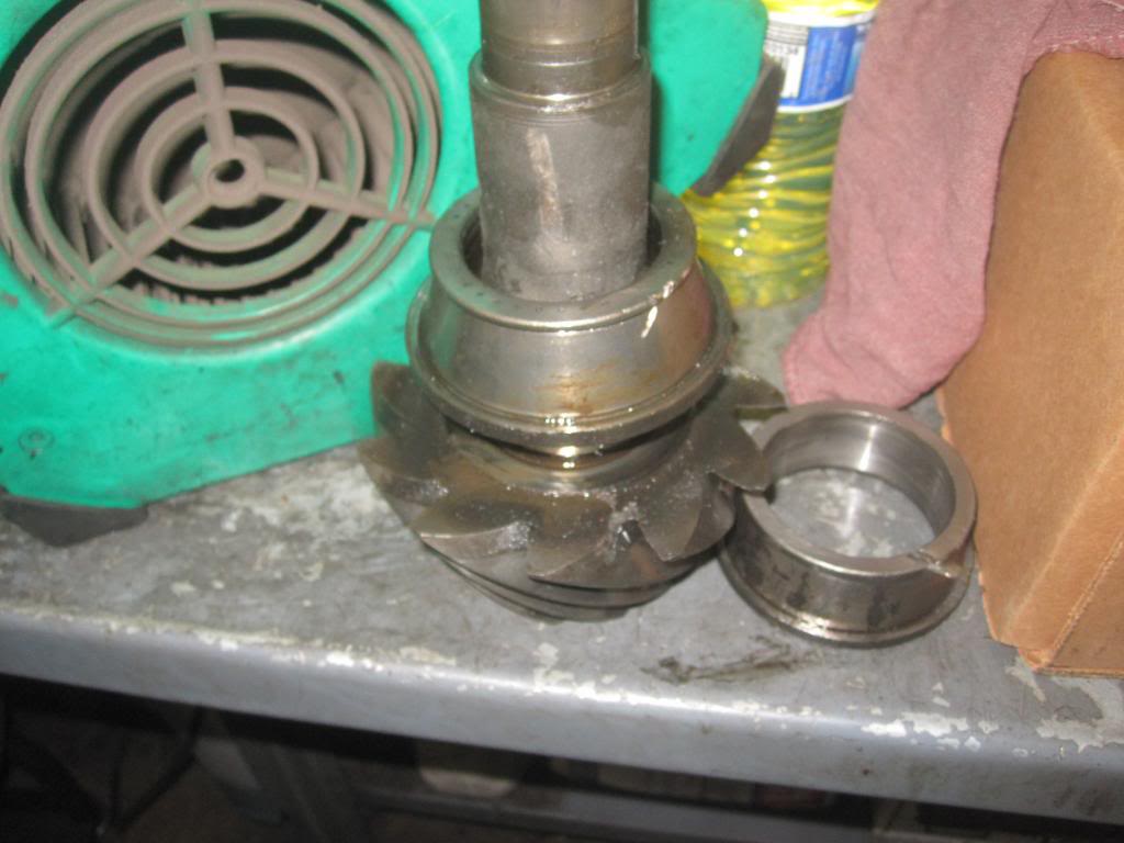
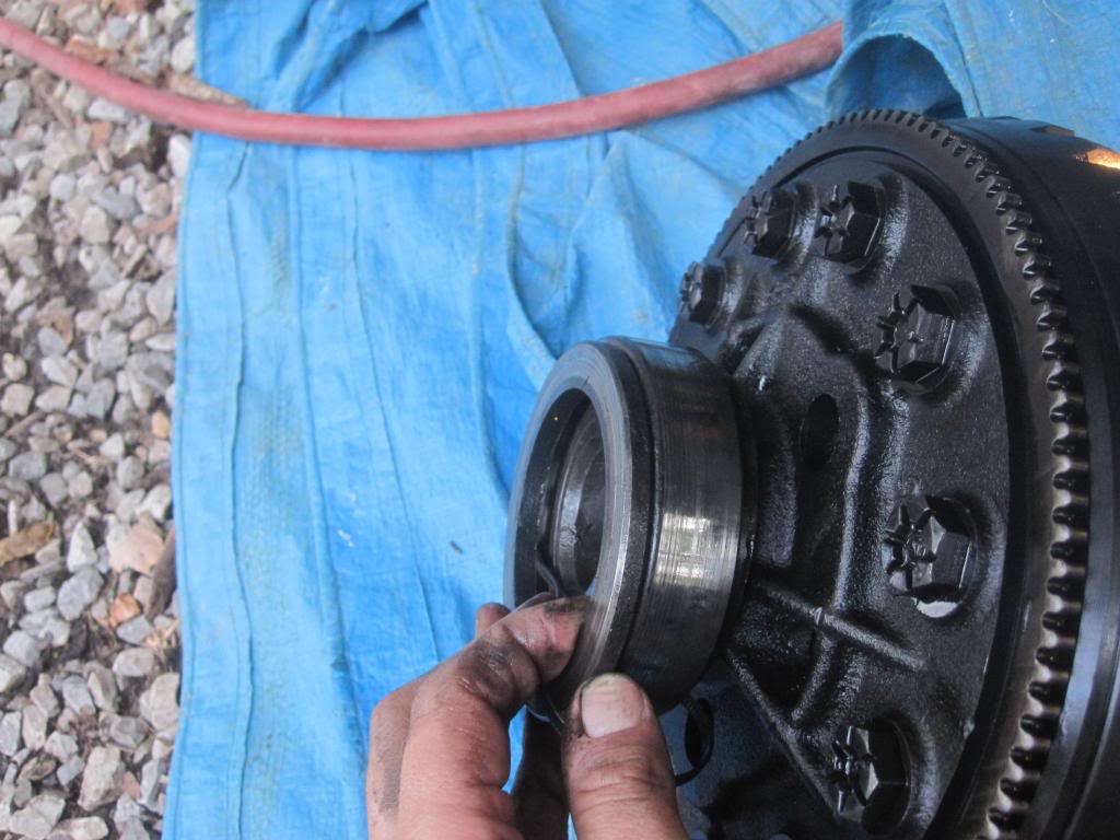
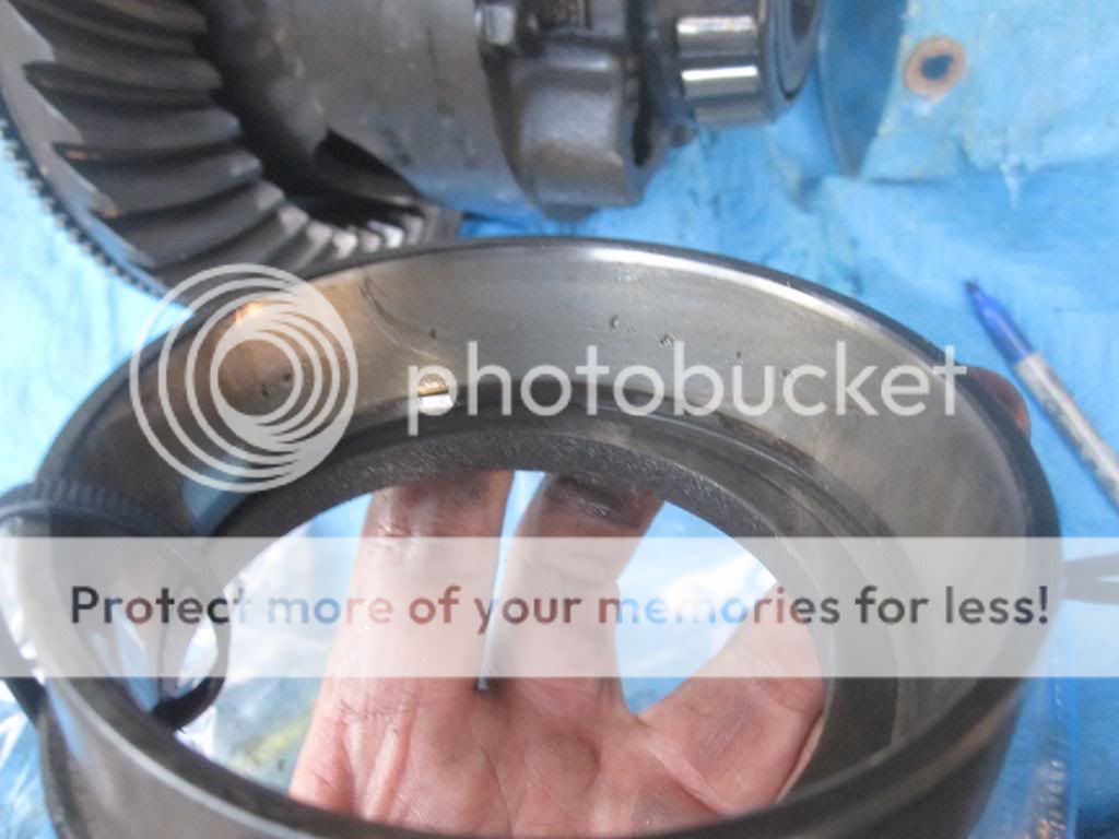
Now you can see the cup (or race) and shim (or washer or spacer) here zip tied together. The bearing cone (with rollers) is of course still on the differential (it will be cut off or pulled off with a hydraulic press).
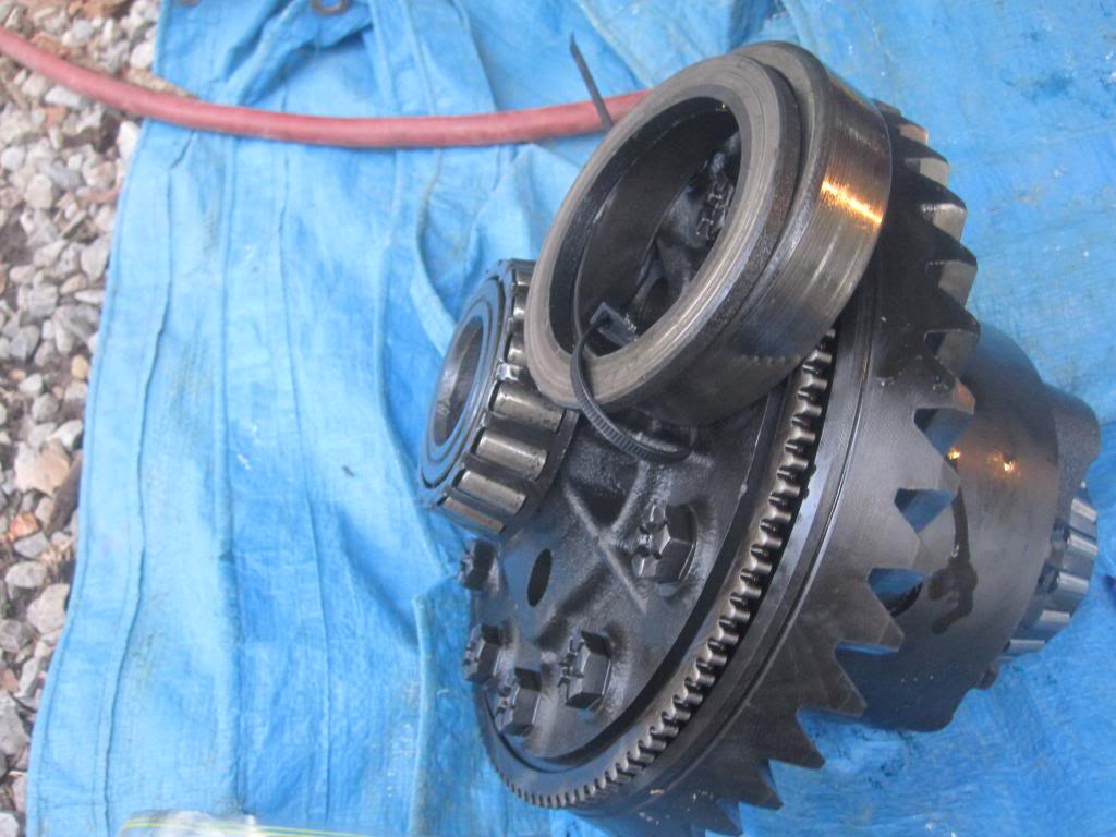
And me holding the race and shim over the bearing which is how it sits under the cap:
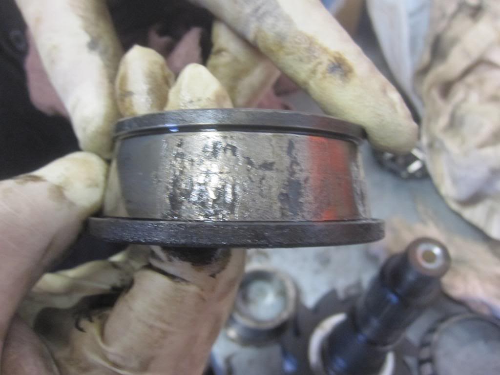
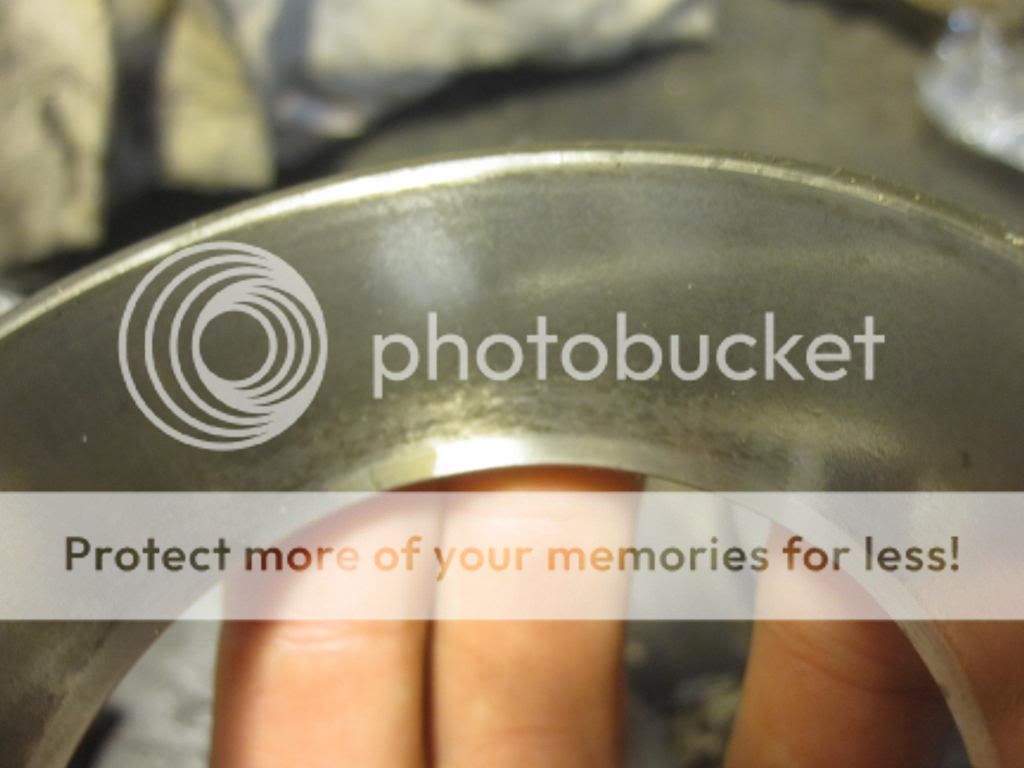
And here is a good example of very pitted cone bearings (see the rollers!) and to a lesser degree, a pitted race. This is the driver's side carrier bearing. By far the worst of the 3 bearings in my diff.
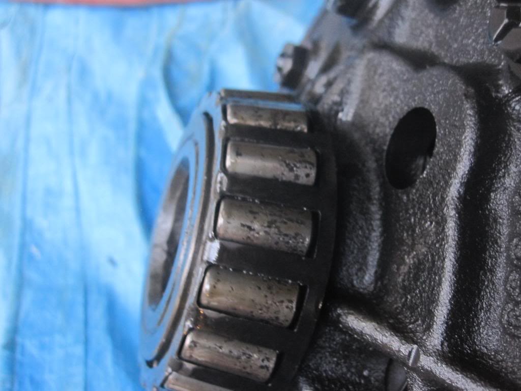
Pitted race:
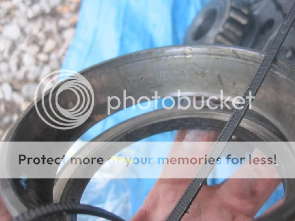
And here is a slightly pitted cone bearing from the passenger side.
and the accompanying race:
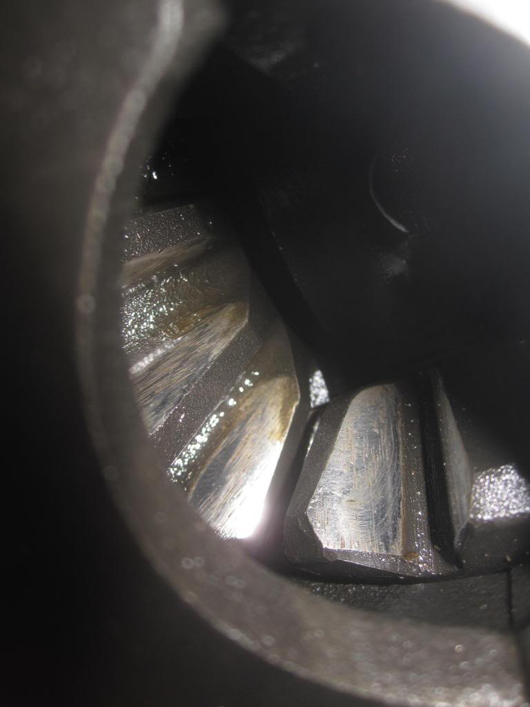
I also found some additional wear in the side gears....I think that's what they are called. They can be seen through the gap in the differential case. The Ford mechanic told me not to be worried, that it wasn’t enough wear to justify changing the side gears.
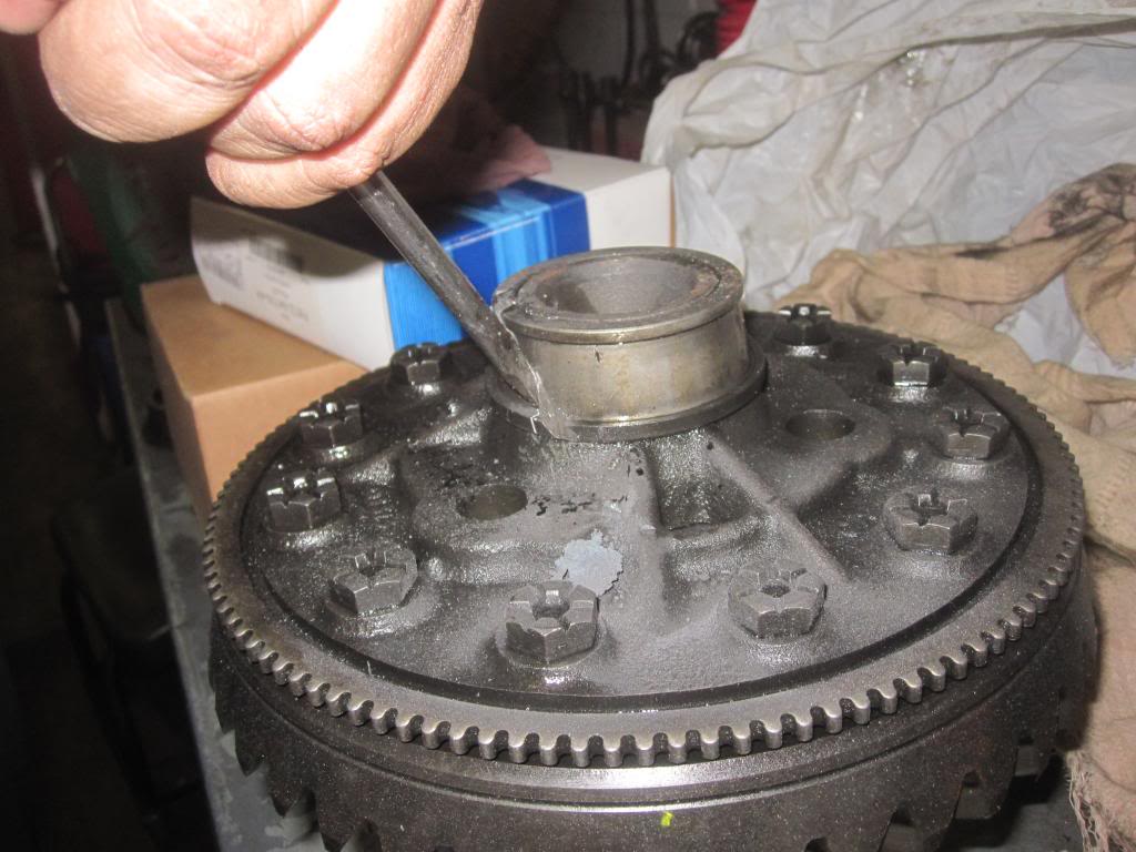
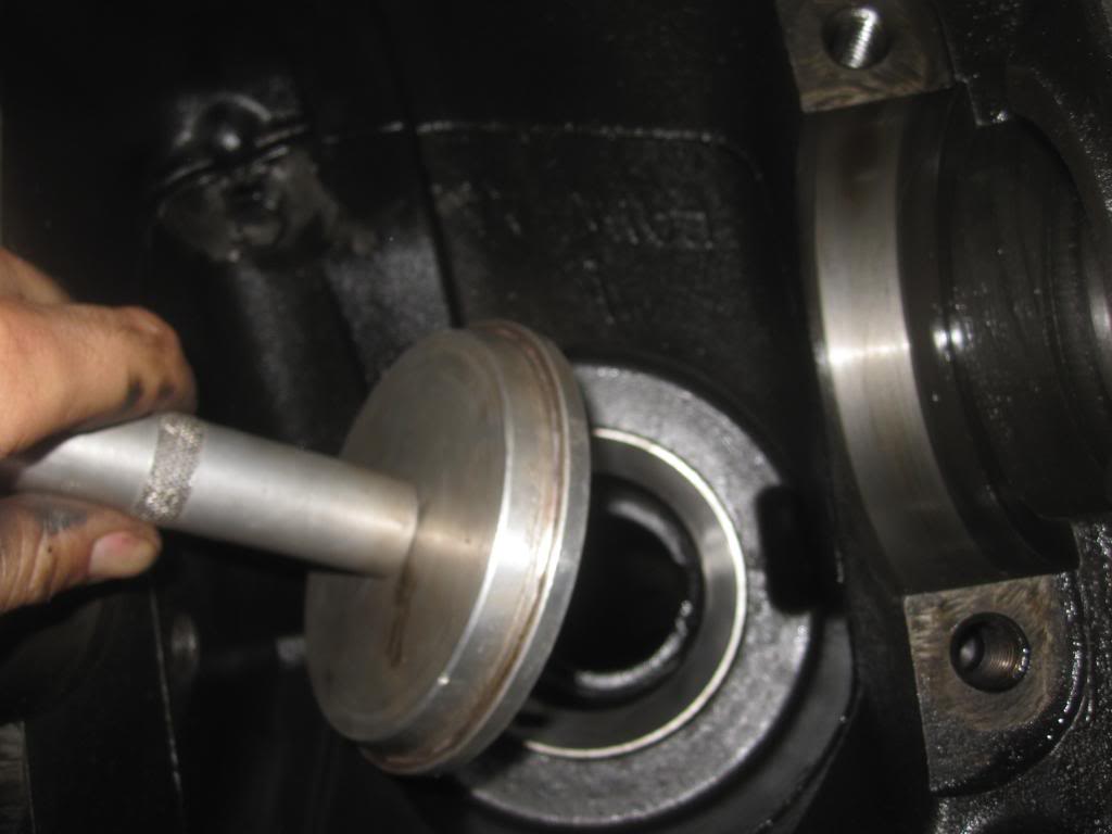
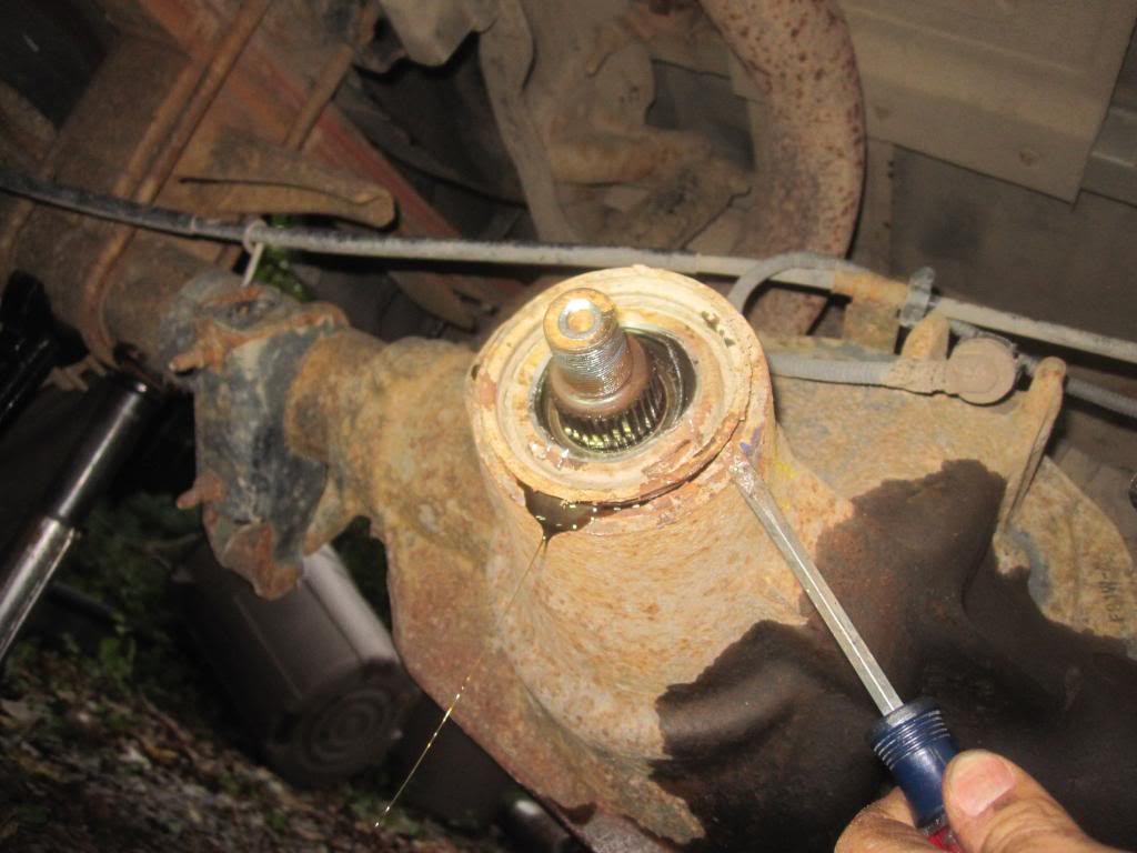
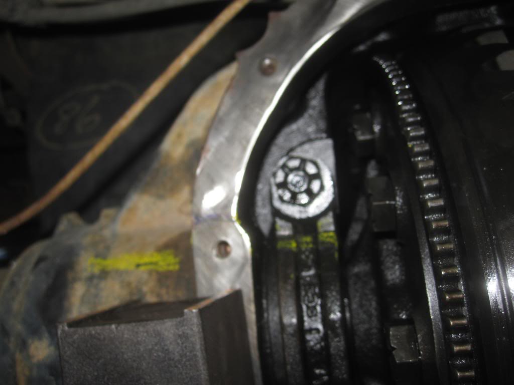
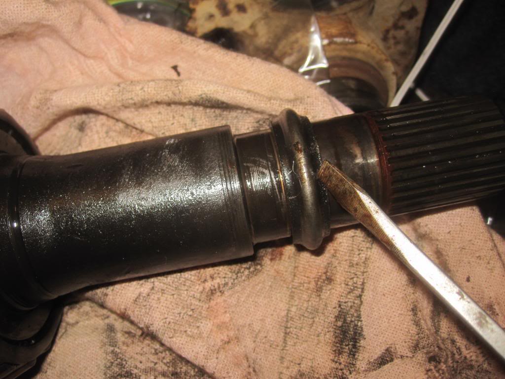
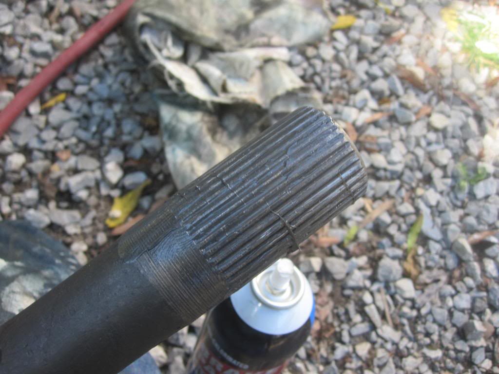
Here is the old crush sleeve mounted on the pinion gear shaft which you need to replace for the rebuild. I am pointing to it with the screwdriver. This gets squeezed and crushed by tightening the pinion nut to create "preload" or more simply put, to get the pinion bearings nice and tight to their respective races but not too tight.
It’s heavy!
Be very careful to make sure the spacers located underneath the caps (they look like large metal washers) don’t fall out when you’re prying out the diff. Pay attention as to which spacer is on which side, label it and put it in a baggie. You will reuse the spacer with the new bearings. Note its orientation under the bracket as well. One or both sides of the shims will have a shaved corner to make installation easier. The shaved corner does towards the outside.
Then you have a mostly empty pumpkin with the exception of the pinion gear which just pulls right though because nothing is holding it place any longer. Ya see the end of the axle which you partially removed earlier sticking through on left side of pic?
And the pumpkin without the pinion gear in it (you can see right through that sucka):
The caps look like this once out of the "pumpkin":
Now you can see the cup (or race) and shim (or washer or spacer) here zip tied together. The bearing cone (with rollers) is of course still on the differential (it will be cut off or pulled off with a hydraulic press).
And me holding the race and shim over the bearing which is how it sits under the cap:
And here is a good example of very pitted cone bearings (see the rollers!) and to a lesser degree, a pitted race. This is the driver's side carrier bearing. By far the worst of the 3 bearings in my diff.
Pitted race:
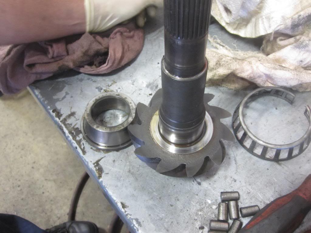
And here is a slightly pitted cone bearing from the passenger side.
and the accompanying race:
I also found some additional wear in the side gears....I think that's what they are called. They can be seen through the gap in the differential case. The Ford mechanic told me not to be worried, that it wasn’t enough wear to justify changing the side gears.
Here is the old crush sleeve mounted on the pinion gear shaft which you need to replace for the rebuild. I am pointing to it with the screwdriver. This gets squeezed and crushed by tightening the pinion nut to create "preload" or more simply put, to get the pinion bearings nice and tight to their respective races but not too tight.
Last edited by Stewart_H; 11-22-2013 at 06:04 PM.
Trending Topics
#8
10-06-2013, 09:53 PM
Continued from above:
In the pics ABOVE, the pinion gear and shaft isn't being held in by much so it kinda slid back down into the pumpkin. You have to push it back through again so the threads show through the front of the pumpkin.
Now you're ready to put the old yoke back on. It doesn't matter which splines you line the yoke up with on the end of the pinion gear shaft since the pinion gear will spin around once you have the yoke back on. I forgot to take pics for this part, sorry. But its easy.
Just make sure to lube the splines with some bearing grease and tap it on there. It doesn't even need to go the entire way on. Just enough so the pinion nut has some threads to catch.
Pre-Loading the Pinion Bearings:
This is the part everyone dreads, but I am not sure why. Seems pretty straightforward to me. I will however admit that this has to be much easier to do with the entire axle out of the truck for reasons I will explain below.
First you take your impact gun and your gonna tighten the NEW (or old pinion nut with Loctite Blue-Medium thread locker. NEW IS PREFERRED) with your impact gun. Guys at Ford told me they often reuse the old nut and use Loctite threadlocker. I recommend getting a new pinion nut as per the official instructions. Who wants to revisit this process even if it is an overpriced ($8) nut?! HELLZ NO. I actually ended up taking off the old pinion nut and putting on a new one.
Now, you want to drive the pinion nut on until it starts to pull the rear pinion bearing cone in towards its cup. Just hit the pinion nut a few dozen times with the impact gun and then check the pinion....it will slap around in the case until the pinion bearing cone makes contact with the cup.
You need to have an INCH POUND torque wrench. NOT THE CLICKER KIND the BEAM KIND. The expensive kind with a dial ($250 plus) or an inexpensive PARK (model TW-1, 0-50 inch pounds) torque wrench. $40 on Amazon. BTW, PARK makes the best tools for bicycles on the market. Pro-grade stuff. Not junk.
The idea is that as you get the bearings tight to the cup by tightening the pinion nut and drawing the pinion gear towards the front of the truck you start to generate resistance to spinning the pinion gear.
The desired resistance for NEW bearings and cups is max of 16-29 INCH POUNDS, for NEW BEARINGS. Its half that if you're just putting a new oil seal on, for example, and leaving all the bearings etc in place and removing and replacing the nut.
You use the small torque wrench to tell you when the resistance to spinning the pinion bearings reaches that "pre-load" setting. Your basically just snugging up the rear bearing CONE to the rear bearing CUP. Too much and it will cause heat and shorten the life of the bearings. To little and it will make a lot of noise (a growling noise).
The impact gun will pull the bearings closer and closer to the cups until it hits the crush sleeve....that�s when the gun starts turning the pinion nut VERY SLOWLY as the gun strains to crush the sleeve.
If you cannot crush the sleeve enough to get 16-29 inch pounds of preload using your impact gun, then you'll need a 2-3 foot breaker bar to crush the sleeve the rest of the way. Most of you probably wont have a strong enough impact gun to do the job.
You'll also need some way to hold the end-yoke/pinion shaft/pinion-gear from spinning while you apply torque to the pinion nut to crush the sleeve. You have a few options. You could:
1. reinstall the axle shafts, put at least one 18mm bolt in to keep it from spinning and drop the rear wheels back onto the ground to keep them from rotating as you torque on the pinion nut. Problem with this method is you will need to remove the axle shafts every time you want to check the preload with the Park torque wrench. Annoying but the cheap way.
2. you could use a large pipe wrench (we all have one of those) and put it on the square part of the yoke end, then use a section of 2x4 or anything hard to put under the pipe wrench so when you squeeze on the pinion nut with you breaker bar the pipe wrench wont spin, allowing you to crush the sleeve little by little.
3. buy a chain strap wrench with a very long handle or in conjunction with a section of pipe to add some length to it and do as #2 above.
4. Or buy an expensive Yoke Wrench:
5. Or this cheaper version you bolt on with the 4 nuts from the yoke plus a breaker bar and section of pipe for added leverage:
"You need to start checking the pre-load torque setting every 1/8th turns of the pinion nut whether using the breaker bar or the impact gun now. Once it�s crushed it cannot be uncrushed...so check often. If you overdo it, its not a huge deal. You will need another crush sleeve ($7, FU Ford!) of course and you can simply reach in and pull the used one out by taking the front pinion bearing out and using a screwdriver to pull the crush sleeve out and put a new one on without taking the entire differential out again."
REMEMBER it�s not the INITIAL torque required to move the pinion bearings that you need to be worried about. It�s the amount of torque you need to KEEP THEM MOVING that is of concern here. This is the preload. The initial torque to start it moving the pinion and bearings will be higher than what it takes to keep them all moving (the pinion gear and bearings spinning). You�ll notice that right away with the torque wrench. First it will read slightly higher and then as you get the bearings spinning it requires less force.
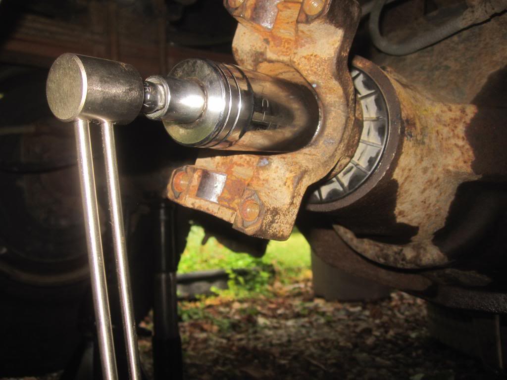
This is were having the entire axle out of the truck would be helpful and probably more accurate. There isn't much space between the pinion and the bottom of the truck, or the fuel tank, which means even with the tiny TW-1 you cant rotate the pinion 360 degrees before hitting something with the torque wrench.
Here is the TW-1 in action. Again, you won�t be able to spin the bearings 360 degrees because even this tiny wrench will hit the fuel tank as you come to 2 o'clock. But that�s probably the best we can do with the entire rear end still on the truck. Any professional installer would take the entire axle down to make this entire job much easier.
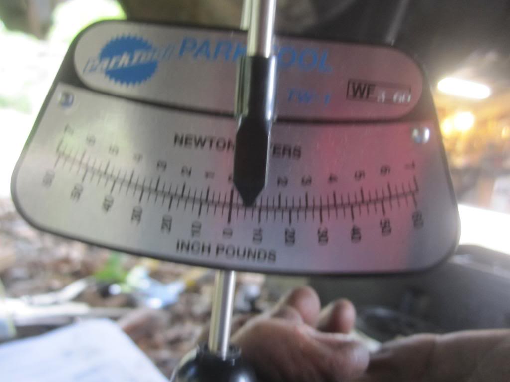
You'll need a reducers to go from 3/8th to 1/2 inch drive. The Park TW-1 comes with a 1/4 to 3/8ths reducer/adapter:
Check the End Yoke
Now grab the end yoke and try and shake it back and forth. It shouldn't move back and forth at all. It should feel solid with the exception of its ability to spin around. No jiggling. No back and forth play (perpendicular to the direction the shaft is pointing). Understand? [If you were to shake the yoke end when the differential is installed in the housing you might feel the pinion gear knocking against the ring gear as the yoke end rotates ever so slightly in your hand. This is the ring gear backlash, that's not what we're worried about. It's hard to move the end yoke back and forth without rotating it. Nonetheless, don't confuse that knocking of gears - backlash- with the need for the end yoke to feel solid in your hand.] Another way to think about it is like this: If the you kicked the drive shaft when the entire thing is put together or on your buddy's truck, it would feel solid. It would not jiggle back and forth. IF IT DOES jiggle around, you haven't squeezed the bearing cone close enough to the cup/race and you need to add more preload (OR your bearing cone might have been damaged when it was pressed onto the pinion gear shaft, which is why you need to have it pressed in place by an experienced installer).
Do not continue until the end yoke has zero lateral play and you have the measured preload correct!
If you move on to the next steps without getting this correct, you will have a growling noise when coasting and you will need to re-tighten the pinion nut and recheck/readjust ring gear backlash (which I talk about below).
Again, tighten the pinion nut until the end yoke doesn't jiggle at all, BUT BE CAREFUL because at this point you're getting close to reaching pinion preload! You need to stop and check with your inch-pound torque wrench often AS SOON AS THAT YOKE END STARTS FEELING SOLID IN YOUR HAND.
This is why I asked you to count the threads protruding past the pinion nut...it will help you know when you're approaching pinion preload.
Check Backlash with Dial Indicator (optional...kinda)
Dial indicators and the magnetic base are CHEAP. This will help confirm that the shims are in the correct position and that you have put the right preload on the pinion bearings. Backlash should be between 8-15 thousands measured on at least 4 teeth and with a variation of no more than 2-3 thousandths total between your 4 measurements. I measured backlash on a dozen teeth. FORD prefes 12-15 thousands as opposed to 8-1.
In the post above I show you how I set up the dial indicator and magnetic base to do this. Its SUPER EASY! Trust me.
If at first the ring gear doesnt rock back and froth just spin the end yoke a few times.
Also, you really dont even need to hold the end yoke to keep it from spinning, while you measure backlash but rather just put a wrench on one of the bolts on the SIDE of the ring gear and just jiggle it back and forth. THAT is your backlash and thats what youre measuring. Its a measure of how close the Pinion Gear and Ring Gear teeth are to one another.
Again, refer back to this great article by Bill BillaVista. He is setting up a DANA differential but the theory is the same. The specs will just be different.
http://www.pirate4x4.com/articles/tech/billavista/Gear_Setup
Paint the Ring Gear Teeth (optional....kinda)
Again: refer back to this great article by Bill BillaVista. http://www.pirate4x4.com/articles/tech/billavista/Gear_Setup
If youve gotten this far you'd be foolish not to invest the 20 minutes it takes to paint a few teeth on the ring gear and spin end yoke around a few times to see how the teeth on the pinion gear are contacting the teeth on the ring gear. This will confirm if youve got everything back together correctly so your gears wont be noisy or even worse, shortlived.
I have some pics in the posts below showing the patterns I got. ITS EASY and fun.
I used Permatex Prussian Blue. YOU MUST ORDER THIS ONLINE. No parts stores have this stuff in stock. You can also use GM or Chrysler's proprietary versions of this. Other companies make their own versions of gear marking compound. Its a non-drying greasy paint.
The master rebuild kits from Yukon come with this paint included . If I had to do this overhaul over I would have gotten an aftermarket rebuild kit. Even wholesale prices at Ford SUCK. You can get pinion and carrier shims, the bearings and the paint from Yukon all for way cheaper than just the bearings from the stealership.
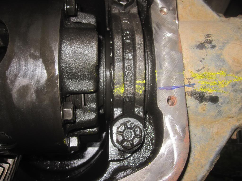
Here are my painted gears. In the first pic the gears are making too much contact towards the outside of the teeth (of the ring gear) on the convex side (the drive side, the side to which force is being applied when you accelerating forwards) and not enough at the base of the teeth (of the ring gear).
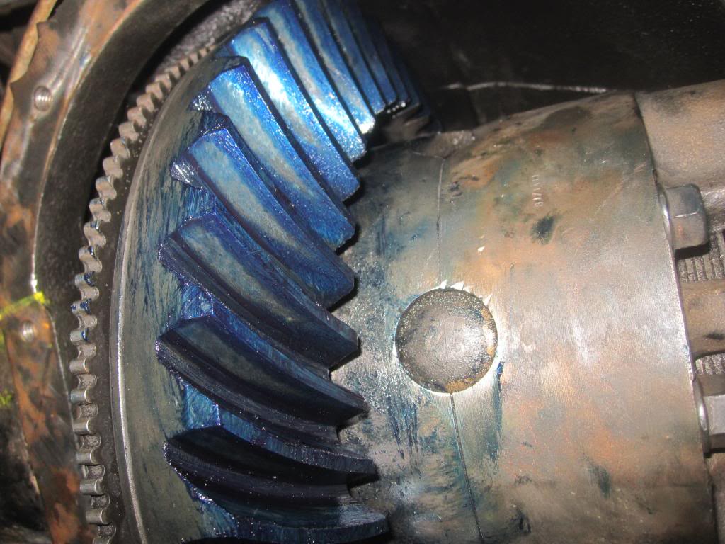
At the same time I was getting too much contact towards the inside of the concave or coast side (the side to which force is being applied when youre coasting along or accelerating in reverse) of the ring gear. Ive read that some mechanics dont pay much attention to the coast side since youre not usually applying force in that direction.:
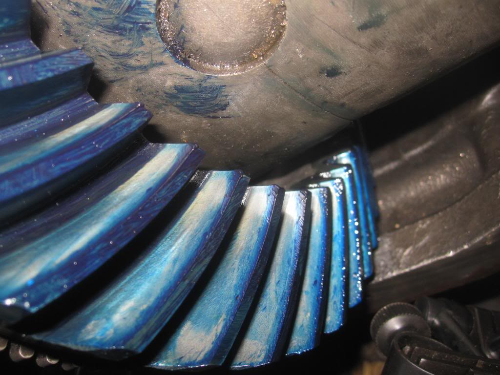
I then had to added some shim thickness, to decrease backlash, to the passenger side of the carrier bearing to push the ring gear over and then I got the correct pattern, as seen here on the drive side. See how the pattern is more centered from the beginning/outisde (root) and end (toe) of the tooth?:
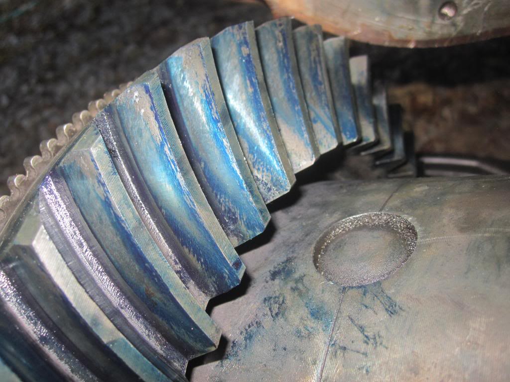
...and the coast side (little bit harder to decipher):
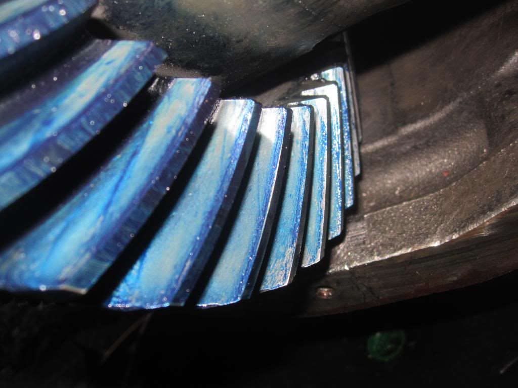
I also pulled the diff out and looked at the pattern on the pinion itself which looks decent:
By painting the gears and spinning them to create these contact patterns you're confirming that youve put everything back together correctly. If your bearing cups haven't spun around in the case and damaged the housing and shims like mine did (you can see pictures of that in the posts below), more than likely you wont need to make any adjustments. You just put it all back together like you found it.
If you DONT get a good a contact pattern, you need to 1. make sure you didnt reverse the shims from left to right on the carrier bearings. Swap them, paint again and check the pattern. 2. make sure that the pinion bearing preload is correct. If thats all correct but your pattern is still no good, read the posts after this one where I add or subtract shims to change the contact pattern.
When youre done just wipe the paint off with a cloth or use brake cleaner and a cloth.
Did you get a good pattern?
Clean the Axle Shafts, Housing and Differential
Now you can clean out your axle and axle shafts, inside the pumpkin, the differential gears...EVERYTHING...with prodigious brake cleaner and compressed air to get any oil and metal out. I used one 14 oz can of brake cleaner per side plus another for the housing.
Or do it later, but before you put the differential back inside the pumpkin so you don't contaminate the differential.
There are plenty of pockets in the diff that hold old oil....get it all out.
Such as between the pinion cups/races:
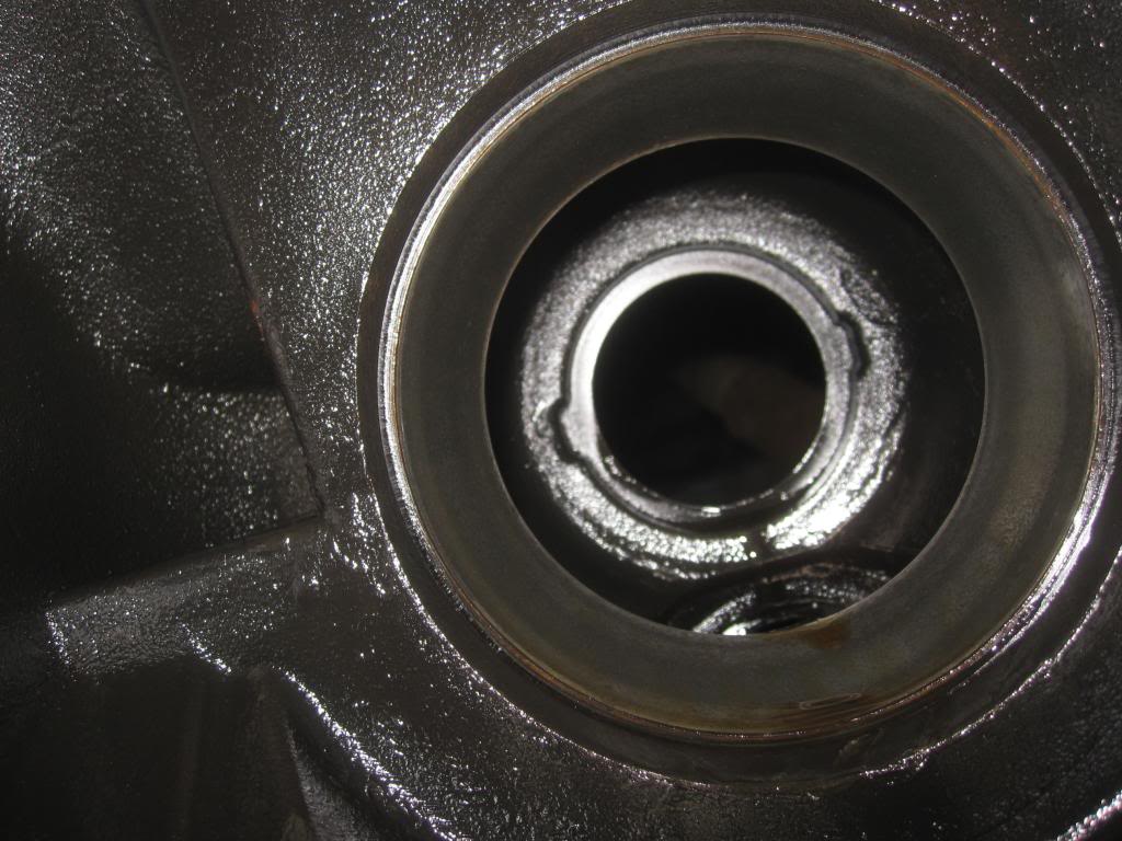
and the bottom of the housing:
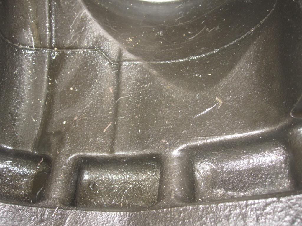
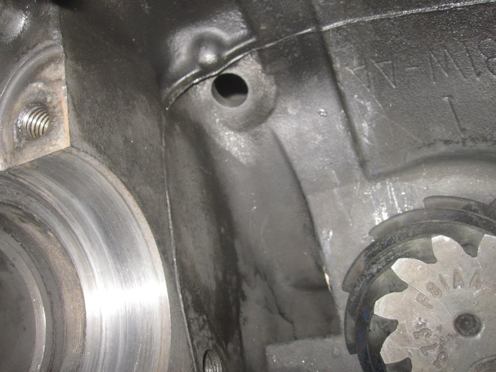
and the left side oil port from the front pinion bearing:
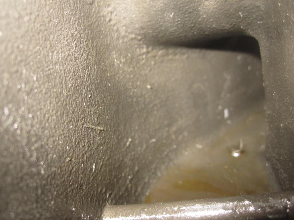
Right side oil journal:

If you have compressed air, spray a can of brake cleaner into each axle side with the axle shafts removed and then blow some air through it. Make sure and put an oil pan under the pumpkin to catch all the brake parts cleaner fluid. You might also push a cloth through with the axle shaft to get the really thick gunk in the bottom of the tube.
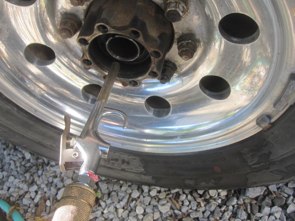
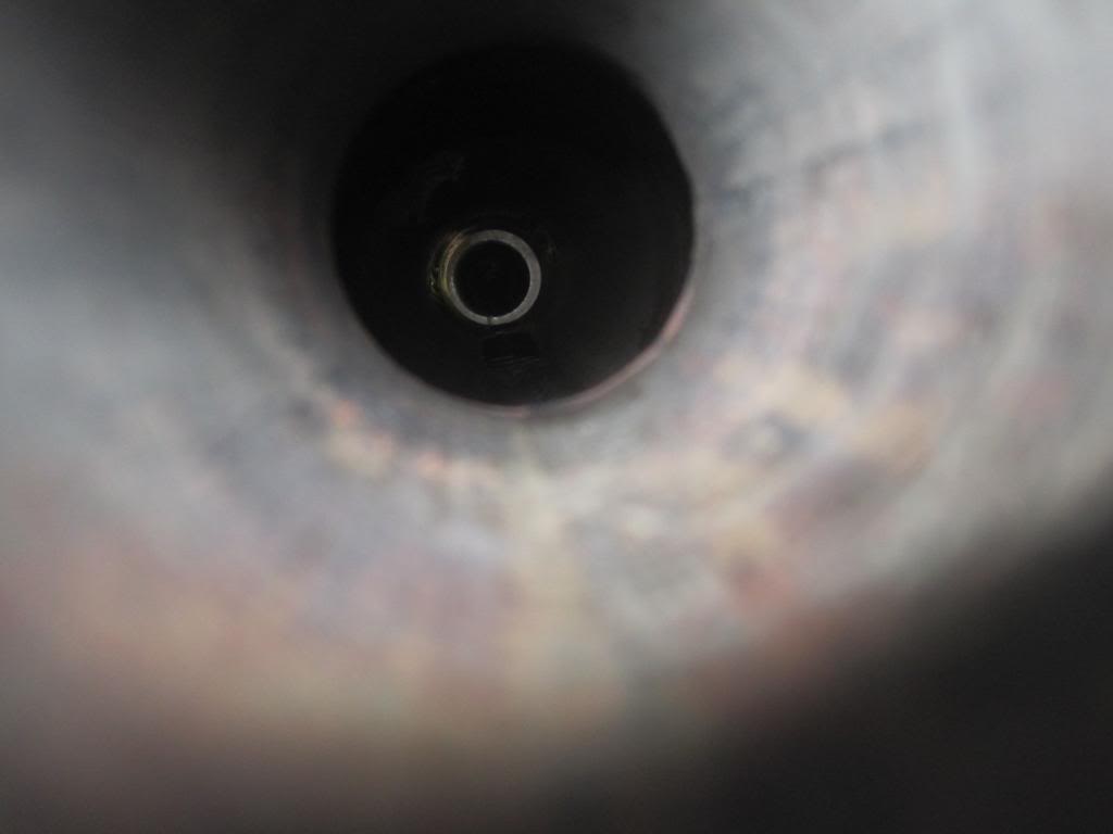
I couldn't get a good photo but with a flashlight you can see right through into the diff housing. In this photo you can see some of the old, thickened, dirty gear lube in the bottom of the shaft. Brake parts cleaner didn't budge this thick stuff.
Make sure and clean the axle shafts themselves as well, plus the splines.
Then inspect your rubber seals for tears or dryness and grease them up with some gear lube.
Inspect the splines for any damage and if they look OK, grease'em up as well.
Reinserting the Differential, Races/Cups and Shims
First, make sure you have no dirt on the diff, or cups or shims. Clean everything off with brake cleaner and a clean rag. No dirt allowed.
The next step is to put the differential with the new carrier bearing cones and cups/races and the original shims/washers in the same orientation as you found them.
First you coat the side of the shims touching the housing with some grease to keep them "glued" to the housing.
With the new cups/races on the cones, you pick up and push the entire differential back into place. It wont just plop right in....if it does...something is wrong. You will need to use a small sledge hammer (2-3 pound) and a piece of wood or a brass hammer to smack the unit back into place. I repeat, it shouldn't just fall into place. If it did, you either mixed up the shims or your carrier bearings have spun and worn themselves thinner, allowing the diff to sit in the housing loosely. If that's the case...as was for me, see below where I attempt top repair spun carrier bearings.
But try and swap the shims and see what happens. If you get a tight fit than you likely just mixed them up.
Carrier Bearing Preload, Say what?!
Remember how we spent all that time setting preload on the pinion bearings? Well, you cant measure preload on the carrier bearings but they sure need preload. They need to be snug. Pirate 4x4 says a couple of blows of a brass hammer is his measure of correct preload (snugness of cone to cup under no load by the engine). My experience was that you need a lot more smacking than that to get it in there.
If your shims looks smooth on both sides and are not grooved (mine were in terrible shape, see pictures in posts below in this same thread and direction on how to proceed), and you haven't mixed up which side they belong on, then you shouldn't worry about carrier preload. Just make sure you have the cups fully around the cones and put it in by hand as far as you can and then start smacking side to side and shimmy it in until the cups are all the way in place.
You'll know when the cups are all the way in because the CAPS (the metal brackets that you carefully labeled for left/right and up/down orientation!) will make FULL CONTACT with the housing where the bolts holes are. If they don't, you haven't gotten the differential in far enough. Keep smacking. If its becoming mission impossible don't keep at...pull the diff out with a pry bar and start again.
Once its in and you think the cups are seated nicely, take a look at the washers, make sure they are all the way in as well and then spin the end yoke a few times in both directions to make sure it spins smoothly without any notchyness. If it feels notchy it may not be in square. Grab your crow bars or pry bars and pull the differential out again and start over.
NEXT, you get the bolts for the caps and tighten them down in an "x pattern" slowly until you get up to 88 ft pounds for each bolt. Spin the end yoke again...make sure it feels smooth in both directions.
Remove Speed Sensor (Optional)
You can remove the speed sensor in order to add the gear oil through the hole on the very top of the pumpkin and not the fill hole in the side of the pumpkin since its much higher up. Your choice.
Remember to wipe off the speed sensor while you have access to it. The speed sensor has magnets in it so enough metal filings on it from wear in the gears will cause your speedometer needle to bounce around. I had this very problem.
It's one bolt...I don't remember what size. Easy to take off. It has a rubber o-ring. Make sure to inspect it, clean it and lube it with some gear oil. I'm sure the Stealership charges $6 for it. Scumbags.
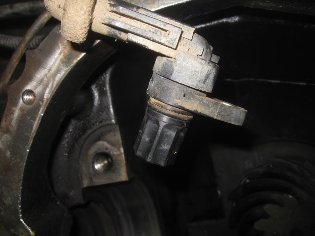
Here is the opening.
Reattach the Driveshaft
Now reattach the drive shaft to the yoke end with the little brackets and bolts. Do this BEFORE you put the axle shafts in, so you can spin the end yoke to match your paint marks from the drive shaft to the paint marks on the end yoke. I didn't take any pics...snooze...its 4 bolts, blue loctite or at least some antiseize.
Then push, kick, the axle shaft back into place...it will take a few blows before the splines go all way into the gears. Spin it around if it isn't going in. Then try pushing it in again.
Then spin your rim/wheel until the holes in the axle shaft flange line up.
Then start putting on the 18mm axle flange bolts, WITH LOCTITE BLUE.
Air ratchet....I love you.
Then torque down to 80 ft pounds in cross pattern.
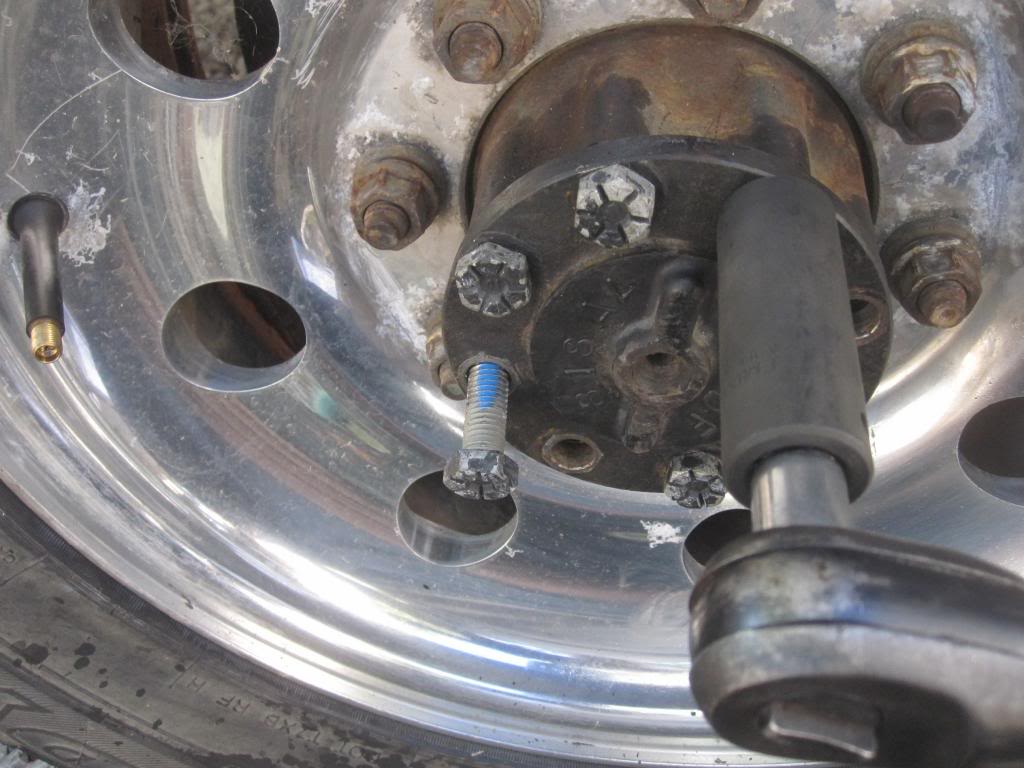
Silicon Gasket Maker (or whatever gasket type you like)
They also sell hard gaskets for this application which personally I would prefer because you dont have to wait for anything to cure / dry, but most mechanics use silicon.
RTV also makes a silicon specifically for differentials:
I used this because it was handy and it available everywhere:
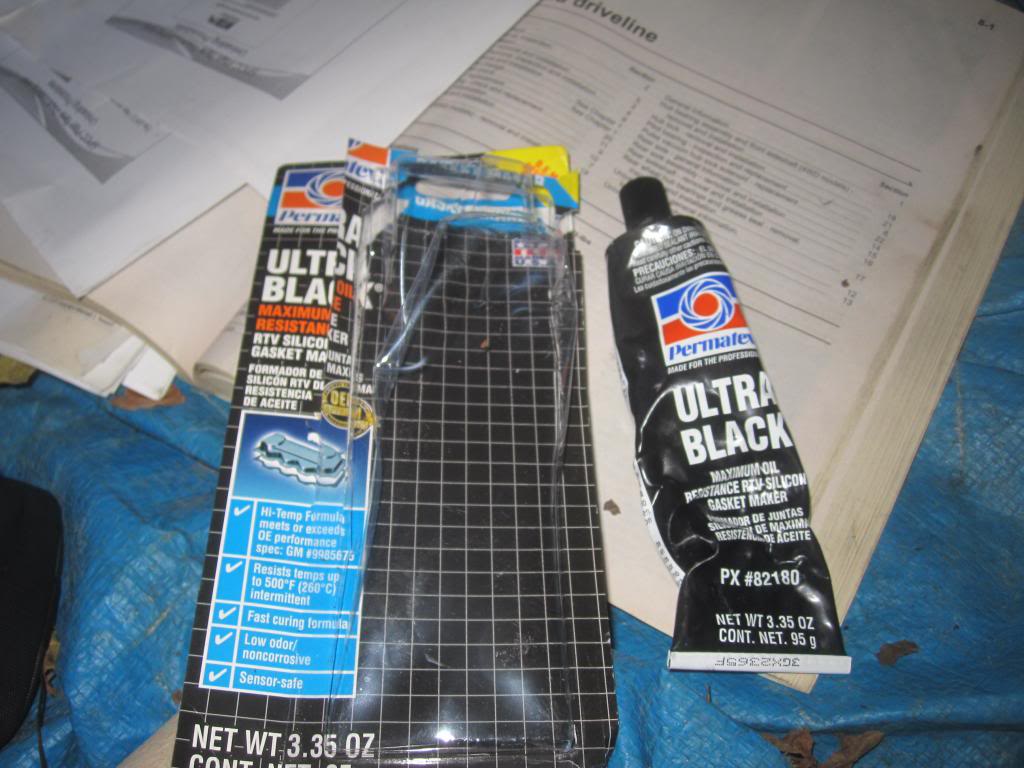
Put on the gasket maker as per picture below....

Then put the CLEANED UP, DIRT FREE cover on immediately, BUT ONLY finger tighten the cover bolts very lightly.
You want the surfaces to make contact with the silicon before it skins over so it adheres well to both surfaces....then let it sit for a 1/2 hour at least. I like to wait 2-4 hours so it has more time to dry.
Then torque the cover bolts to specs (29-39 foot pounds). Some silicon will squeeze out. Just wipe off the excess and you're done.
Add Gear Oil
Next, add 3.5 quarts of SYNTHETIC 75-140 gear oil through the speed sensor hole or the side fill hole.
Mobil1 comes with friction modifier / hypoid gear silencer already in it. If your oil doesn't have modifier in it, you'll need to buy some from FORD or aftermarket and add 4 ounces of this to your gear oil.
Then put the speed sensor back on and tighten. Don't go crazy tightening it. The 0-ring does all the sealing. Making it over tight doesn't help. If you used the side filler hole, as is customary, its 15-20 ft-pounds to tighten it back on using a 3/8th inch-drive.
Spun Carrier Bearings: A side Story
As you can see from the posts below, my bearing cups / races had spun in the housing from a lack of proper lubrication. Below I attempt to repair the axle. Keep reading if you like. The last owner was bringing the truck to a well known national lube chain, and apparently they didn't do the oil changes they were paid to do. This caused the bearings to get pitted, which increased friction and caused the cups to spin around and release lots of metal into the oil and also created an extremely loud whining noise at speeds above 15 MPH but only when accelerating.
In the pics ABOVE, the pinion gear and shaft isn't being held in by much so it kinda slid back down into the pumpkin. You have to push it back through again so the threads show through the front of the pumpkin.
Now you're ready to put the old yoke back on. It doesn't matter which splines you line the yoke up with on the end of the pinion gear shaft since the pinion gear will spin around once you have the yoke back on. I forgot to take pics for this part, sorry. But its easy.
Just make sure to lube the splines with some bearing grease and tap it on there. It doesn't even need to go the entire way on. Just enough so the pinion nut has some threads to catch.
Pre-Loading the Pinion Bearings:
This is the part everyone dreads, but I am not sure why. Seems pretty straightforward to me. I will however admit that this has to be much easier to do with the entire axle out of the truck for reasons I will explain below.
First you take your impact gun and your gonna tighten the NEW (or old pinion nut with Loctite Blue-Medium thread locker. NEW IS PREFERRED) with your impact gun. Guys at Ford told me they often reuse the old nut and use Loctite threadlocker. I recommend getting a new pinion nut as per the official instructions. Who wants to revisit this process even if it is an overpriced ($8) nut?! HELLZ NO. I actually ended up taking off the old pinion nut and putting on a new one.
Now, you want to drive the pinion nut on until it starts to pull the rear pinion bearing cone in towards its cup. Just hit the pinion nut a few dozen times with the impact gun and then check the pinion....it will slap around in the case until the pinion bearing cone makes contact with the cup.
You need to have an INCH POUND torque wrench. NOT THE CLICKER KIND the BEAM KIND. The expensive kind with a dial ($250 plus) or an inexpensive PARK (model TW-1, 0-50 inch pounds) torque wrench. $40 on Amazon. BTW, PARK makes the best tools for bicycles on the market. Pro-grade stuff. Not junk.
The idea is that as you get the bearings tight to the cup by tightening the pinion nut and drawing the pinion gear towards the front of the truck you start to generate resistance to spinning the pinion gear.
The desired resistance for NEW bearings and cups is max of 16-29 INCH POUNDS, for NEW BEARINGS. Its half that if you're just putting a new oil seal on, for example, and leaving all the bearings etc in place and removing and replacing the nut.
You use the small torque wrench to tell you when the resistance to spinning the pinion bearings reaches that "pre-load" setting. Your basically just snugging up the rear bearing CONE to the rear bearing CUP. Too much and it will cause heat and shorten the life of the bearings. To little and it will make a lot of noise (a growling noise).
The impact gun will pull the bearings closer and closer to the cups until it hits the crush sleeve....that�s when the gun starts turning the pinion nut VERY SLOWLY as the gun strains to crush the sleeve.
If you cannot crush the sleeve enough to get 16-29 inch pounds of preload using your impact gun, then you'll need a 2-3 foot breaker bar to crush the sleeve the rest of the way. Most of you probably wont have a strong enough impact gun to do the job.
You'll also need some way to hold the end-yoke/pinion shaft/pinion-gear from spinning while you apply torque to the pinion nut to crush the sleeve. You have a few options. You could:
1. reinstall the axle shafts, put at least one 18mm bolt in to keep it from spinning and drop the rear wheels back onto the ground to keep them from rotating as you torque on the pinion nut. Problem with this method is you will need to remove the axle shafts every time you want to check the preload with the Park torque wrench. Annoying but the cheap way.
2. you could use a large pipe wrench (we all have one of those) and put it on the square part of the yoke end, then use a section of 2x4 or anything hard to put under the pipe wrench so when you squeeze on the pinion nut with you breaker bar the pipe wrench wont spin, allowing you to crush the sleeve little by little.
3. buy a chain strap wrench with a very long handle or in conjunction with a section of pipe to add some length to it and do as #2 above.
4. Or buy an expensive Yoke Wrench:
5. Or this cheaper version you bolt on with the 4 nuts from the yoke plus a breaker bar and section of pipe for added leverage:
"You need to start checking the pre-load torque setting every 1/8th turns of the pinion nut whether using the breaker bar or the impact gun now. Once it�s crushed it cannot be uncrushed...so check often. If you overdo it, its not a huge deal. You will need another crush sleeve ($7, FU Ford!) of course and you can simply reach in and pull the used one out by taking the front pinion bearing out and using a screwdriver to pull the crush sleeve out and put a new one on without taking the entire differential out again."
REMEMBER it�s not the INITIAL torque required to move the pinion bearings that you need to be worried about. It�s the amount of torque you need to KEEP THEM MOVING that is of concern here. This is the preload. The initial torque to start it moving the pinion and bearings will be higher than what it takes to keep them all moving (the pinion gear and bearings spinning). You�ll notice that right away with the torque wrench. First it will read slightly higher and then as you get the bearings spinning it requires less force.
This is were having the entire axle out of the truck would be helpful and probably more accurate. There isn't much space between the pinion and the bottom of the truck, or the fuel tank, which means even with the tiny TW-1 you cant rotate the pinion 360 degrees before hitting something with the torque wrench.
Here is the TW-1 in action. Again, you won�t be able to spin the bearings 360 degrees because even this tiny wrench will hit the fuel tank as you come to 2 o'clock. But that�s probably the best we can do with the entire rear end still on the truck. Any professional installer would take the entire axle down to make this entire job much easier.
You'll need a reducers to go from 3/8th to 1/2 inch drive. The Park TW-1 comes with a 1/4 to 3/8ths reducer/adapter:
Check the End Yoke
Now grab the end yoke and try and shake it back and forth. It shouldn't move back and forth at all. It should feel solid with the exception of its ability to spin around. No jiggling. No back and forth play (perpendicular to the direction the shaft is pointing). Understand? [If you were to shake the yoke end when the differential is installed in the housing you might feel the pinion gear knocking against the ring gear as the yoke end rotates ever so slightly in your hand. This is the ring gear backlash, that's not what we're worried about. It's hard to move the end yoke back and forth without rotating it. Nonetheless, don't confuse that knocking of gears - backlash- with the need for the end yoke to feel solid in your hand.] Another way to think about it is like this: If the you kicked the drive shaft when the entire thing is put together or on your buddy's truck, it would feel solid. It would not jiggle back and forth. IF IT DOES jiggle around, you haven't squeezed the bearing cone close enough to the cup/race and you need to add more preload (OR your bearing cone might have been damaged when it was pressed onto the pinion gear shaft, which is why you need to have it pressed in place by an experienced installer).
Do not continue until the end yoke has zero lateral play and you have the measured preload correct!
If you move on to the next steps without getting this correct, you will have a growling noise when coasting and you will need to re-tighten the pinion nut and recheck/readjust ring gear backlash (which I talk about below).
Again, tighten the pinion nut until the end yoke doesn't jiggle at all, BUT BE CAREFUL because at this point you're getting close to reaching pinion preload! You need to stop and check with your inch-pound torque wrench often AS SOON AS THAT YOKE END STARTS FEELING SOLID IN YOUR HAND.
This is why I asked you to count the threads protruding past the pinion nut...it will help you know when you're approaching pinion preload.
Check Backlash with Dial Indicator (optional...kinda)
Dial indicators and the magnetic base are CHEAP. This will help confirm that the shims are in the correct position and that you have put the right preload on the pinion bearings. Backlash should be between 8-15 thousands measured on at least 4 teeth and with a variation of no more than 2-3 thousandths total between your 4 measurements. I measured backlash on a dozen teeth. FORD prefes 12-15 thousands as opposed to 8-1.
In the post above I show you how I set up the dial indicator and magnetic base to do this. Its SUPER EASY! Trust me.
If at first the ring gear doesnt rock back and froth just spin the end yoke a few times.
Also, you really dont even need to hold the end yoke to keep it from spinning, while you measure backlash but rather just put a wrench on one of the bolts on the SIDE of the ring gear and just jiggle it back and forth. THAT is your backlash and thats what youre measuring. Its a measure of how close the Pinion Gear and Ring Gear teeth are to one another.
Again, refer back to this great article by Bill BillaVista. He is setting up a DANA differential but the theory is the same. The specs will just be different.
http://www.pirate4x4.com/articles/tech/billavista/Gear_Setup
Paint the Ring Gear Teeth (optional....kinda)
Again: refer back to this great article by Bill BillaVista. http://www.pirate4x4.com/articles/tech/billavista/Gear_Setup
If youve gotten this far you'd be foolish not to invest the 20 minutes it takes to paint a few teeth on the ring gear and spin end yoke around a few times to see how the teeth on the pinion gear are contacting the teeth on the ring gear. This will confirm if youve got everything back together correctly so your gears wont be noisy or even worse, shortlived.
I have some pics in the posts below showing the patterns I got. ITS EASY and fun.
I used Permatex Prussian Blue. YOU MUST ORDER THIS ONLINE. No parts stores have this stuff in stock. You can also use GM or Chrysler's proprietary versions of this. Other companies make their own versions of gear marking compound. Its a non-drying greasy paint.
The master rebuild kits from Yukon come with this paint included . If I had to do this overhaul over I would have gotten an aftermarket rebuild kit. Even wholesale prices at Ford SUCK. You can get pinion and carrier shims, the bearings and the paint from Yukon all for way cheaper than just the bearings from the stealership.
Here are my painted gears. In the first pic the gears are making too much contact towards the outside of the teeth (of the ring gear) on the convex side (the drive side, the side to which force is being applied when you accelerating forwards) and not enough at the base of the teeth (of the ring gear).
At the same time I was getting too much contact towards the inside of the concave or coast side (the side to which force is being applied when youre coasting along or accelerating in reverse) of the ring gear. Ive read that some mechanics dont pay much attention to the coast side since youre not usually applying force in that direction.:
I then had to added some shim thickness, to decrease backlash, to the passenger side of the carrier bearing to push the ring gear over and then I got the correct pattern, as seen here on the drive side. See how the pattern is more centered from the beginning/outisde (root) and end (toe) of the tooth?:
...and the coast side (little bit harder to decipher):
I also pulled the diff out and looked at the pattern on the pinion itself which looks decent:
By painting the gears and spinning them to create these contact patterns you're confirming that youve put everything back together correctly. If your bearing cups haven't spun around in the case and damaged the housing and shims like mine did (you can see pictures of that in the posts below), more than likely you wont need to make any adjustments. You just put it all back together like you found it.
If you DONT get a good a contact pattern, you need to 1. make sure you didnt reverse the shims from left to right on the carrier bearings. Swap them, paint again and check the pattern. 2. make sure that the pinion bearing preload is correct. If thats all correct but your pattern is still no good, read the posts after this one where I add or subtract shims to change the contact pattern.
When youre done just wipe the paint off with a cloth or use brake cleaner and a cloth.
Did you get a good pattern?
Clean the Axle Shafts, Housing and Differential
Now you can clean out your axle and axle shafts, inside the pumpkin, the differential gears...EVERYTHING...with prodigious brake cleaner and compressed air to get any oil and metal out. I used one 14 oz can of brake cleaner per side plus another for the housing.
Or do it later, but before you put the differential back inside the pumpkin so you don't contaminate the differential.
There are plenty of pockets in the diff that hold old oil....get it all out.
Such as between the pinion cups/races:
and the bottom of the housing:
and the left side oil port from the front pinion bearing:
Right side oil journal:
If you have compressed air, spray a can of brake cleaner into each axle side with the axle shafts removed and then blow some air through it. Make sure and put an oil pan under the pumpkin to catch all the brake parts cleaner fluid. You might also push a cloth through with the axle shaft to get the really thick gunk in the bottom of the tube.
I couldn't get a good photo but with a flashlight you can see right through into the diff housing. In this photo you can see some of the old, thickened, dirty gear lube in the bottom of the shaft. Brake parts cleaner didn't budge this thick stuff.
Make sure and clean the axle shafts themselves as well, plus the splines.
Then inspect your rubber seals for tears or dryness and grease them up with some gear lube.
Inspect the splines for any damage and if they look OK, grease'em up as well.
Reinserting the Differential, Races/Cups and Shims
First, make sure you have no dirt on the diff, or cups or shims. Clean everything off with brake cleaner and a clean rag. No dirt allowed.
The next step is to put the differential with the new carrier bearing cones and cups/races and the original shims/washers in the same orientation as you found them.
First you coat the side of the shims touching the housing with some grease to keep them "glued" to the housing.
With the new cups/races on the cones, you pick up and push the entire differential back into place. It wont just plop right in....if it does...something is wrong. You will need to use a small sledge hammer (2-3 pound) and a piece of wood or a brass hammer to smack the unit back into place. I repeat, it shouldn't just fall into place. If it did, you either mixed up the shims or your carrier bearings have spun and worn themselves thinner, allowing the diff to sit in the housing loosely. If that's the case...as was for me, see below where I attempt top repair spun carrier bearings.
But try and swap the shims and see what happens. If you get a tight fit than you likely just mixed them up.
Carrier Bearing Preload, Say what?!
Remember how we spent all that time setting preload on the pinion bearings? Well, you cant measure preload on the carrier bearings but they sure need preload. They need to be snug. Pirate 4x4 says a couple of blows of a brass hammer is his measure of correct preload (snugness of cone to cup under no load by the engine). My experience was that you need a lot more smacking than that to get it in there.
If your shims looks smooth on both sides and are not grooved (mine were in terrible shape, see pictures in posts below in this same thread and direction on how to proceed), and you haven't mixed up which side they belong on, then you shouldn't worry about carrier preload. Just make sure you have the cups fully around the cones and put it in by hand as far as you can and then start smacking side to side and shimmy it in until the cups are all the way in place.
You'll know when the cups are all the way in because the CAPS (the metal brackets that you carefully labeled for left/right and up/down orientation!) will make FULL CONTACT with the housing where the bolts holes are. If they don't, you haven't gotten the differential in far enough. Keep smacking. If its becoming mission impossible don't keep at...pull the diff out with a pry bar and start again.
Once its in and you think the cups are seated nicely, take a look at the washers, make sure they are all the way in as well and then spin the end yoke a few times in both directions to make sure it spins smoothly without any notchyness. If it feels notchy it may not be in square. Grab your crow bars or pry bars and pull the differential out again and start over.
NEXT, you get the bolts for the caps and tighten them down in an "x pattern" slowly until you get up to 88 ft pounds for each bolt. Spin the end yoke again...make sure it feels smooth in both directions.
Remove Speed Sensor (Optional)
You can remove the speed sensor in order to add the gear oil through the hole on the very top of the pumpkin and not the fill hole in the side of the pumpkin since its much higher up. Your choice.
Remember to wipe off the speed sensor while you have access to it. The speed sensor has magnets in it so enough metal filings on it from wear in the gears will cause your speedometer needle to bounce around. I had this very problem.
It's one bolt...I don't remember what size. Easy to take off. It has a rubber o-ring. Make sure to inspect it, clean it and lube it with some gear oil. I'm sure the Stealership charges $6 for it. Scumbags.

Here is the opening.
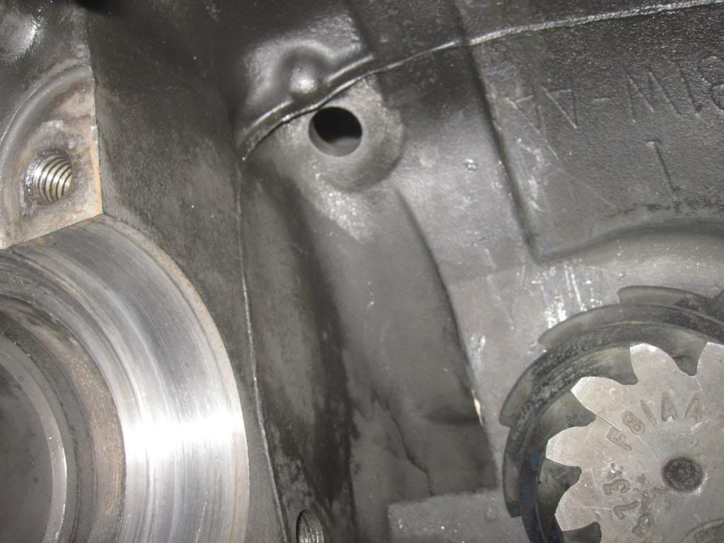
Reattach the Driveshaft
Now reattach the drive shaft to the yoke end with the little brackets and bolts. Do this BEFORE you put the axle shafts in, so you can spin the end yoke to match your paint marks from the drive shaft to the paint marks on the end yoke. I didn't take any pics...snooze...its 4 bolts, blue loctite or at least some antiseize.
Then push, kick, the axle shaft back into place...it will take a few blows before the splines go all way into the gears. Spin it around if it isn't going in. Then try pushing it in again.
Then spin your rim/wheel until the holes in the axle shaft flange line up.
Then start putting on the 18mm axle flange bolts, WITH LOCTITE BLUE.
Air ratchet....I love you.
Then torque down to 80 ft pounds in cross pattern.
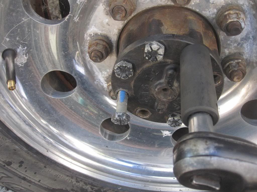
Silicon Gasket Maker (or whatever gasket type you like)
They also sell hard gaskets for this application which personally I would prefer because you dont have to wait for anything to cure / dry, but most mechanics use silicon.
RTV also makes a silicon specifically for differentials:
I used this because it was handy and it available everywhere:

Put on the gasket maker as per picture below....
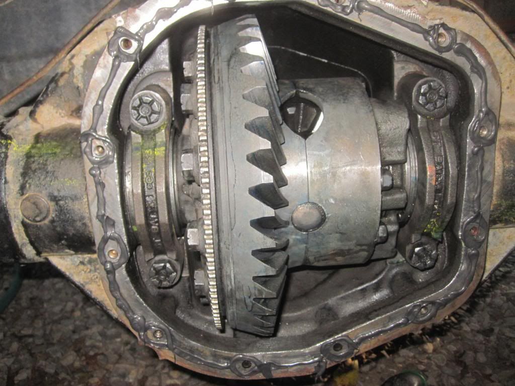
Then put the CLEANED UP, DIRT FREE cover on immediately, BUT ONLY finger tighten the cover bolts very lightly.
You want the surfaces to make contact with the silicon before it skins over so it adheres well to both surfaces....then let it sit for a 1/2 hour at least. I like to wait 2-4 hours so it has more time to dry.
Then torque the cover bolts to specs (29-39 foot pounds). Some silicon will squeeze out. Just wipe off the excess and you're done.
Add Gear Oil
Next, add 3.5 quarts of SYNTHETIC 75-140 gear oil through the speed sensor hole or the side fill hole.
Mobil1 comes with friction modifier / hypoid gear silencer already in it. If your oil doesn't have modifier in it, you'll need to buy some from FORD or aftermarket and add 4 ounces of this to your gear oil.
Then put the speed sensor back on and tighten. Don't go crazy tightening it. The 0-ring does all the sealing. Making it over tight doesn't help. If you used the side filler hole, as is customary, its 15-20 ft-pounds to tighten it back on using a 3/8th inch-drive.
Spun Carrier Bearings: A side Story
As you can see from the posts below, my bearing cups / races had spun in the housing from a lack of proper lubrication. Below I attempt to repair the axle. Keep reading if you like. The last owner was bringing the truck to a well known national lube chain, and apparently they didn't do the oil changes they were paid to do. This caused the bearings to get pitted, which increased friction and caused the cups to spin around and release lots of metal into the oil and also created an extremely loud whining noise at speeds above 15 MPH but only when accelerating.
Last edited by Stewart_H; 11-12-2013 at 11:39 PM.

#10
10-07-2013, 01:29 PM
WOW, Lex...great details man  . Hope all goes well with it. I went the other route. Was in your shoes a month ago. Due to time, i just went and found another axle. I did however, after reading about the crush sleeve install, went with a sleeve eliminator kit. Once set, you can swap out yokes and not worry about the backlash setting. I went that way because of the ungodly force needed to crush the darn thing. Something in the neighborhood of 450#-600# needed. Help using a 6ft cheater bar.
. Hope all goes well with it. I went the other route. Was in your shoes a month ago. Due to time, i just went and found another axle. I did however, after reading about the crush sleeve install, went with a sleeve eliminator kit. Once set, you can swap out yokes and not worry about the backlash setting. I went that way because of the ungodly force needed to crush the darn thing. Something in the neighborhood of 450#-600# needed. Help using a 6ft cheater bar.
#11
10-07-2013, 03:05 PM
WOW, Lex...great details man . Hope all goes well with it. I went the other route. Was in your shoes a month ago. Due to time, i just went and found another axle. I did however, after reading about the crush sleeve install, went with a sleeve eliminator kit. Once set, you can swap out yokes and not worry about the backlash setting. I went that way because of the ungodly force needed to crush the darn thing. Something in the neighborhood of 450#-600# needed. Help using a 6ft cheater bar.
. Hope all goes well with it. I went the other route. Was in your shoes a month ago. Due to time, i just went and found another axle. I did however, after reading about the crush sleeve install, went with a sleeve eliminator kit. Once set, you can swap out yokes and not worry about the backlash setting. I went that way because of the ungodly force needed to crush the darn thing. Something in the neighborhood of 450#-600# needed. Help using a 6ft cheater bar.I do understand the risk involved....I could blow up the entire axle. BUT, the 2 professional mechanics I know, one FORD one independent, both said..."nah...its easy many, you can do it..." and thats all I needed to hear.
Oh so you don't have the sterling/visteon 10.5? The Dana diff has that absurdly high pinion nut torque setting...right? you need a 6 foot bar to make that much torque!
#12
10-07-2013, 03:06 PM
#13
10-07-2013, 05:51 PM
No, i got the 10.5. But that much torque is needed to collapse the crush sleeve. And from what i've read and pics to go along with it, an impact just cant cut it. Not try'n to reign on your parade, bro just throw'n out there what i've read / "learned". Its why i went the crush sleeve eliminator kit, way.
#14
10-07-2013, 05:59 PM
One of them is currently in the process of doing an engine rebuild, and like you, is also sharing it here.
Pop
#15
10-07-2013, 06:35 PM
No, i got the 10.5. But that much torque is needed to collapse the crush sleeve. And from what i've read and pics to go along with it, an impact just cant cut it. Not try'n to reign on your parade, bro just throw'n out there what i've read / "learned". Its why i went the crush sleeve eliminator kit, way.
Thoughts?
Listen, I am not pretending to be an expert on any aspect of this. I am asking, learning and soliciting input. If someone thinks I am doing something wrong PLEASE SAY SO. I want to make sure the instructions are correct.