Trying to find a bad fusible link: what tools do I need?
#1
 09-02-2013, 10:44 AM


Join Date: Jun 2010
Location: Balt. Co, MD
Posts: 235
Likes: 0
Received 0 Likes
on
0 Posts
Trying to find a bad fusible link: what tools do I need?
I have a bad fusible link for my rear lights. I'm pretty bad with electrical circuit theory and such, so can anyone tell me what tools I'll need to figure this out? I am guessing a non-contact continuity tester, but I'm looking online and I'm not sure if I'm looking for the right thing, or if they are available for DC current. Any help appreciated. Thanks.
Here are two I've found online, local parts store don't seem to carry any:
Here are two I've found online, local parts store don't seem to carry any:
Last edited by ericconn; 09-02-2013 at 10:50 AM. Reason: add links
#2
09-02-2013, 12:46 PM

What are you working on? Is this the '84 in your profile? Typically fusible links are only positioned at the start of the main electrical feed or alternator output, and are designed to protect heavy-gauge wiring upstream of the fuse panel and into the ignition switch. Lighter-gauge wiring is protected by the fuse panel, or is unfused. Rear lighting is not protected by a fusible link; typically the turn signal and stop lights are fused and the running lights are breakered. A multimeter can check continuity of a fusible link or fuse.
What is the specific problem you're facing?
What is the specific problem you're facing?
#3
09-02-2013, 01:15 PM
Join Date: Jun 2010
Location: Balt. Co, MD
Posts: 235
Likes: 0
Received 0 Likes
on
0 Posts
What are you working on? Is this the '84 in your profile? Typically fusible links are only positioned at the start of the main electrical feed or alternator output, and are designed to protect heavy-gauge wiring upstream of the fuse panel and into the ignition switch. Lighter-gauge wiring is protected by the fuse panel, or is unfused. Rear lighting is not protected by a fusible link; typically the turn signal and stop lights are fused and the running lights are breakered. A multimeter can check continuity of a fusible link or fuse.
What is the specific problem you're facing?
What is the specific problem you're facing?
#4
09-02-2013, 05:04 PM
#5
09-02-2013, 06:28 PM
Join Date: Jun 2010
Location: Balt. Co, MD
Posts: 235
Likes: 0
Received 0 Likes
on
0 Posts
On the diagram I have, fuse #1 is for instrument panel illumination and is only a 5 amp fuse.
Are you sure you are looking at fuse #1? There should be no need to pull the fuse panel to find the wire color. If you find the correct fuse in your diagram, it will show the color of the wire.
Are you sure you are looking at fuse #1? There should be no need to pull the fuse panel to find the wire color. If you find the correct fuse in your diagram, it will show the color of the wire.
#6
09-02-2013, 07:50 PM
Thanks for that picture. Yes, Chilton's numbered the fuses differently, but the function and positions are the same as mine. Mine(which I think is the Ford designation) is F13, 15 amp, Emergency and Stoplamps.
This circuit is a hot all the time circuit, and is fed by a large yellow wire that leads through the harness to a splice somewhere under the dash. This splice has at least 3 yellow wires on it. This splice feeds your 15 amp circuit, the ignition switch power, and the other wire leads out to a fusible link at the battery/solenoid area(still a yellow wire).
If you have stuff working when you turn the keyswitch, then your fusible link is good, since you must have power at the splice for the ignition switch.
Have you taken the fuse out and used a meter to probe both contacts in the fuse socket? And you have no power on either one with the fuse out?
#7
09-02-2013, 10:46 PM
Join Date: Jun 2010
Location: Balt. Co, MD
Posts: 235
Likes: 0
Received 0 Likes
on
0 Posts
Thanks for that picture. Yes, Chilton's numbered the fuses differently, but the function and positions are the same as mine. Mine(which I think is the Ford designation) is F13, 15 amp, Emergency and Stoplamps.
This circuit is a hot all the time circuit, and is fed by a large yellow wire that leads through the harness to a splice somewhere under the dash. This splice has at least 3 yellow wires on it. This splice feeds your 15 amp circuit, the ignition switch power, and the other wire leads out to a fusible link at the battery/solenoid area(still a yellow wire).
If you have stuff working when you turn the keyswitch, then your fusible link is good, since you must have power at the splice for the ignition switch.
Have you taken the fuse out and used a meter to probe both contacts in the fuse socket? And you have no power on either one with the fuse out?
This circuit is a hot all the time circuit, and is fed by a large yellow wire that leads through the harness to a splice somewhere under the dash. This splice has at least 3 yellow wires on it. This splice feeds your 15 amp circuit, the ignition switch power, and the other wire leads out to a fusible link at the battery/solenoid area(still a yellow wire).
If you have stuff working when you turn the keyswitch, then your fusible link is good, since you must have power at the splice for the ignition switch.
Have you taken the fuse out and used a meter to probe both contacts in the fuse socket? And you have no power on either one with the fuse out?
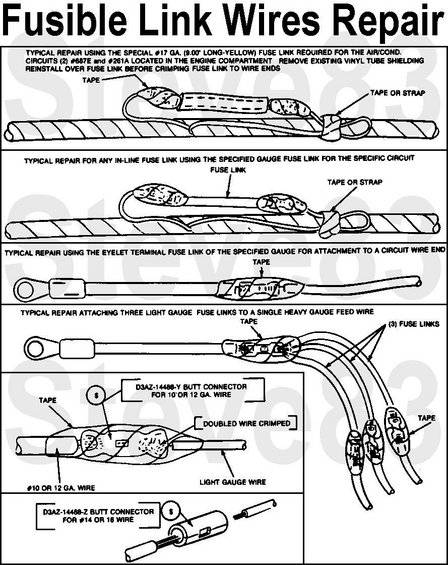
And just to be clear, one of the legs of the yellow spliced wire feeds into the back of the fuse box for this 15A fuse? In the Chilton there's a diagram on repairing fusible links, which I can put on here, that shows a large wire with three splices, each of them with a fusible link in them. This wire wouldn't have that going on would it? I just don't know how only one leg would get fried but the other would be fine, if there wasn't something like a fusible link in there, because all the other stuff that you say is on that wire works. Again, circuits are not my strong suit, so I apologize if I'm missing something in my understand. Thanks again, I'll test tomorrow evening and let you know if I have any luck.
Trending Topics
#8
09-03-2013, 11:38 AM
Join Date: Jun 2010
Location: Balt. Co, MD
Posts: 235
Likes: 0
Received 0 Likes
on
0 Posts
Here's the diagram with the three-wire setup, from this site: 1983 Ford Bronco Diagrams picture | SuperMotors.net
#9
09-03-2013, 03:06 PM
Here's a diagram of a later truck, but it's close to your diesel.

You can see where the yellow wire leads off the starter relay and goes to the #1 fuse. That's the only place you will have a fusible link in this wire. In this setup you can see right below that wire is another yellow wire that feeds the ignition switch. So your truck may be like that, or it might have the splice under the dash, I don't know.

You can see where the yellow wire leads off the starter relay and goes to the #1 fuse. That's the only place you will have a fusible link in this wire. In this setup you can see right below that wire is another yellow wire that feeds the ignition switch. So your truck may be like that, or it might have the splice under the dash, I don't know.
#10
09-03-2013, 07:35 PM
Join Date: Jun 2010
Location: Balt. Co, MD
Posts: 235
Likes: 0
Received 0 Likes
on
0 Posts
Okay, so I figured out what one problem was. The socket for the rear lights wasn't snug, so I fixed that and I now have good hazard light function in all four corners. I still can't get the meter to show anything when I probe that 15A fuse, I'm just probably not getting good contact.
However, now when I use the turn signal, the front turn signals react correctly, but now in the rear both turn signals blink, as do the license plate lights, and the blinking speed is slightly faster than when it's just the front blinking. Any idea what this is a symptom of? A grounding issue?
However, now when I use the turn signal, the front turn signals react correctly, but now in the rear both turn signals blink, as do the license plate lights, and the blinking speed is slightly faster than when it's just the front blinking. Any idea what this is a symptom of? A grounding issue?
#11
09-03-2013, 07:42 PM
The blinker works on bulb load. The more bulbs hooked in the system, the faster it will blink. Less bulbs means it will blink slower, and not enough bulb load and it will not blink at all, it will just stay on solid. That's why when you hook a trailer up, you usually need to get a heavy duty blinker so the lights won't blink so fast with the added bulb load from the trailer.
On your rear light problem, something sounds wired wrong, or one of the bulbs is not correctly oriented in the socket, bridging some of the contacts. The license plate lights have nothing to do with this circuit. I believe someone has wired something wrong at the back of the truck.
The license plate lights, and the running lights, are all fed from one single brown wire that comes down the driver's side frame rail. It's a very simple circuit.
You should then have two different colored wires, one to each taillight. These are the brake/turn wires. And then you will have one more wire that goes to each taillight, that will be the reverse lamps.
#12
09-03-2013, 07:52 PM
Join Date: Jun 2010
Location: Balt. Co, MD
Posts: 235
Likes: 0
Received 0 Likes
on
0 Posts
Ok great, thanks a lot. Something must be wired wrong if the license plate lights are blinking. Me/my family is the second owner of this truck since 1985 or so, and we never messed with the harness, but there are some wires that are cut that come out of the harness. I guess the PO must have tried to put in lights for towing. I picked up a 4-flat towing towing adapter last week. I can use that to isolate the problem to the lighting harness or the supply wires (Right?).
#13
09-03-2013, 08:32 PM
Join Date: Jun 2010
Location: Balt. Co, MD
Posts: 235
Likes: 0
Received 0 Likes
on
0 Posts
I just tried the towing adapter, and something I did along the way got everything to work properly. I now have correct blinking in all four corners. There must be a slightly bad connection somewhere that I'll have to chase down eventually, I think in the left turn signal wire and maybe also the ground. Thanks again for your help.
#14
09-25-2013, 12:58 AM

Sounds like a bad ground. What is probably happening is your back feeding through the base of your 1157 bulbs into your taillamp circuit which will get you to a ground someplace in the system. That is the reason you want to test your brake turnsignal lights with your tail lights turned on. Doing that will show you bad grounds every time.

Thread
Thread Starter
Forum
Replies
Last Post
truckerbear
1987 - 1996 F150 & Larger F-Series Trucks
6
08-08-2012 12:30 PM
frdlvr35
1973 - 1979 F-100 & Larger F-Series Trucks
12
01-27-2011 06:32 PM