223 I6 alternator conversion
#1
 08-20-2013, 03:31 PM


Join Date: Apr 2013
Location: Bay Area, CA
Posts: 45
Likes: 0
Received 0 Likes
on
0 Posts
Hello all, I just finished an alternator conversion on my truck and everything turned out well so I thought I should share it with you guys.
So first off after reading a couple threads on here I figured going with a GM alternator would be adequate. So I found a rebuilt one from autozone with a lifetime warranty. Its a 2 wire with an internal regulator (1982 Chevrolet Truck C10 1/2 ton P/U 2WD 5.0L Carburetor OHV 8cyl part #DL7127M)
I used the existing brackets and modified them to do the job.
Also my generator and voltage regulator are now available so PM if interested.
Using the bottom bracket I needed the following hardware:
12" rod (3/8"-16 thread) I cut it to length.
Then you need 4, 3/8"-16 grade 8 nuts.
Using the top bracket I needed the following hardware:
2, 1/4" split washers that are a 1/4 inch thick.
1, 1/4" flat washer.
1, 1/4" bolt that's at least 2 inches long.
Tools you will need:
Electric/pneumatic grinder
Electric drill
step drill bit
3/8" drill bit
Bench Vice
deep socket 9/16 inch and wrench/spanner
socket wrench
1/2 inch socket and wrench/spanner
3/8 inch socket and wrench/spanner
11/16 inch socket and wrench/spanner
12 inch groove/channel lock pliers
wire cutters/strippers
assorted wire terminals
12 volt diode
a roll of 12 gauge red wire
volt meter
Bubble level or the app for your smart phone
safety glasses and gloves
Fire extinguisher
Now for the how to
- Prewiring Setup -
First start off by disconnecting the battery completely.
Then remove all wires connected to the old generator, there should be 3 if I remember correctly.
Once that's done remove the 1/4" bolt from on top of the generator, once removed slide the generator towards the engine and remove the belt.
Now you are able to move beneath the generator, looseb the 2, 11/16th bolts on both sides of the bottom brackets using a wrench/spanner to hold the 2 inside nuts I believe they're 9/16ths.
Now once you just about have those bolts almost out have your buddy support that generator from above so it doesn't fall and knock you out
Now you are able to remove that bottom generator bracket, use 11/16th sockets on both bolts and remove the bracket.
Take your bracket and place it in your bench vice to begin drilling. measure 1-1/4" from the center of one of the holes, mark the position and start drilling first with a 3/8" bit to start the hole then use a step drill bit to match the diameter of the existing holes on the bracket.
- THESE MEASUREMENTS MAY BE DIFFERENT FOR YOUR SET UP SO MAKE SURE TO TEST FIT BEFORE MAKING ANY IRREVERSIBLE MODIFICATIONS, USE MY MEASUREMENTS ONLY AS A GUIDE -
Now that you have modified that bracket you are now able to put it back on the engine block. For me the engine block moved a little from the front mount near the radiator so I had a buddy use a channel/groove lock wrench to move the mount back place using the engine as a leverage to line up the bolt hole. Once he lined it up I was able to thread the bolt and place the bracket back on.
At this point you may be wondering how this bottom bracket will hold the new alternator stable with only on bolt, but there is no need to worry because the top bracket will serve that purpose of not allowing it to rotate. use your level now to level the bottom bracket.
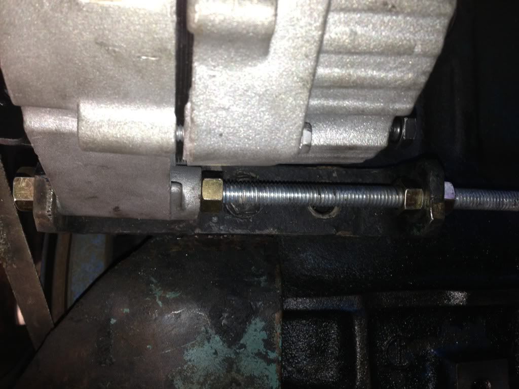
Next take your 3/8" rod and cut it between 8"-10"
Take that rod and thread 2 of those 3/8 bolts on. Thread them both to the middle.
Now place the rod through the back hole of the bracket first, then place it through the bottom of the alternator first and then through thread the rod through the front of the bracket.
Once you have the rod in place, thread a nut on the front of the rod on the outside of the bracket near the radiator, make sure that the rod sits flush with the end of the nut or else it will destroy your fan belt.
Now that the rod is in place thread one of the nuts towards the alternator and the other towards the end of the bracket. Finally place your last 3/8" nut on the outside of the bracket on the end of the rod closest to the cab.
Tip: doing this while the alternator is rotated down towards the ground makes tightening the nuts much easier.
Tighten all nuts. Keep in mind keeping the rod flush with the outside front nut! and also keeping the alternator flush with the inside of the bracket!
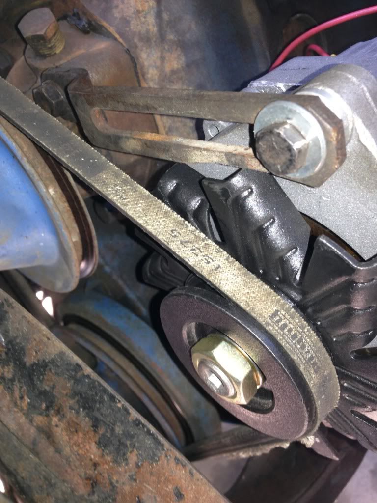
Loosen the top bracket and push it down as far as possible.
Swing the alternator towards the top bracket and thread that 1/4" bolt that bolt through the bracket using a flat washer between the bracket and the bolt head and then sandwiching those 2 split washers between the bracket and the alternator.
Keep in mind you want the alternator rotated all the way at the end of the top bracket (far right if you're facing the cab) because that's where you'll have the tightest belt.
Now the alternator fan will rub against both the top and the bottom bracket find these points on both brackets and mark it. remove your bottom alternator and rod and begin to grind off little by little to give more clearance. Make sure to test fit after every 1/8 inch grinned away.
- KEEP EXTINGUISHER HANDER FOR THESE STEPS! -
repeat on the top bracket also. Just to give you an idea about how much I ended up grinding, on the top bracket it was about a 1/4" and the bottom was about 1/4" - 1/2"
Tip: Grind in a scooping motion that matches the circular shape of the alternator fan.
Once you've cleared enough space for the fan to rotate. proceed to slipping on the belt and tighten everything.
The hardest part is done.
So first off after reading a couple threads on here I figured going with a GM alternator would be adequate. So I found a rebuilt one from autozone with a lifetime warranty. Its a 2 wire with an internal regulator (1982 Chevrolet Truck C10 1/2 ton P/U 2WD 5.0L Carburetor OHV 8cyl part #DL7127M)
I used the existing brackets and modified them to do the job.
Also my generator and voltage regulator are now available so PM if interested.
Using the bottom bracket I needed the following hardware:
12" rod (3/8"-16 thread) I cut it to length.
Then you need 4, 3/8"-16 grade 8 nuts.
Using the top bracket I needed the following hardware:
2, 1/4" split washers that are a 1/4 inch thick.
1, 1/4" flat washer.
1, 1/4" bolt that's at least 2 inches long.
Tools you will need:
Electric/pneumatic grinder
Electric drill
step drill bit
3/8" drill bit
Bench Vice
deep socket 9/16 inch and wrench/spanner
socket wrench
1/2 inch socket and wrench/spanner
3/8 inch socket and wrench/spanner
11/16 inch socket and wrench/spanner
12 inch groove/channel lock pliers
wire cutters/strippers
assorted wire terminals
12 volt diode
a roll of 12 gauge red wire
volt meter
Bubble level or the app for your smart phone
safety glasses and gloves
Fire extinguisher
Now for the how to
- Prewiring Setup -
First start off by disconnecting the battery completely.
Then remove all wires connected to the old generator, there should be 3 if I remember correctly.
Once that's done remove the 1/4" bolt from on top of the generator, once removed slide the generator towards the engine and remove the belt.
Now you are able to move beneath the generator, looseb the 2, 11/16th bolts on both sides of the bottom brackets using a wrench/spanner to hold the 2 inside nuts I believe they're 9/16ths.
Now once you just about have those bolts almost out have your buddy support that generator from above so it doesn't fall and knock you out
Now you are able to remove that bottom generator bracket, use 11/16th sockets on both bolts and remove the bracket.
Take your bracket and place it in your bench vice to begin drilling. measure 1-1/4" from the center of one of the holes, mark the position and start drilling first with a 3/8" bit to start the hole then use a step drill bit to match the diameter of the existing holes on the bracket.
- THESE MEASUREMENTS MAY BE DIFFERENT FOR YOUR SET UP SO MAKE SURE TO TEST FIT BEFORE MAKING ANY IRREVERSIBLE MODIFICATIONS, USE MY MEASUREMENTS ONLY AS A GUIDE -
Now that you have modified that bracket you are now able to put it back on the engine block. For me the engine block moved a little from the front mount near the radiator so I had a buddy use a channel/groove lock wrench to move the mount back place using the engine as a leverage to line up the bolt hole. Once he lined it up I was able to thread the bolt and place the bracket back on.
At this point you may be wondering how this bottom bracket will hold the new alternator stable with only on bolt, but there is no need to worry because the top bracket will serve that purpose of not allowing it to rotate. use your level now to level the bottom bracket.
Next take your 3/8" rod and cut it between 8"-10"
Take that rod and thread 2 of those 3/8 bolts on. Thread them both to the middle.
Now place the rod through the back hole of the bracket first, then place it through the bottom of the alternator first and then through thread the rod through the front of the bracket.
Once you have the rod in place, thread a nut on the front of the rod on the outside of the bracket near the radiator, make sure that the rod sits flush with the end of the nut or else it will destroy your fan belt.
Now that the rod is in place thread one of the nuts towards the alternator and the other towards the end of the bracket. Finally place your last 3/8" nut on the outside of the bracket on the end of the rod closest to the cab.
Tip: doing this while the alternator is rotated down towards the ground makes tightening the nuts much easier.
Tighten all nuts. Keep in mind keeping the rod flush with the outside front nut! and also keeping the alternator flush with the inside of the bracket!
Loosen the top bracket and push it down as far as possible.
Swing the alternator towards the top bracket and thread that 1/4" bolt that bolt through the bracket using a flat washer between the bracket and the bolt head and then sandwiching those 2 split washers between the bracket and the alternator.
Keep in mind you want the alternator rotated all the way at the end of the top bracket (far right if you're facing the cab) because that's where you'll have the tightest belt.
Now the alternator fan will rub against both the top and the bottom bracket find these points on both brackets and mark it. remove your bottom alternator and rod and begin to grind off little by little to give more clearance. Make sure to test fit after every 1/8 inch grinned away.
- KEEP EXTINGUISHER HANDER FOR THESE STEPS! -
repeat on the top bracket also. Just to give you an idea about how much I ended up grinding, on the top bracket it was about a 1/4" and the bottom was about 1/4" - 1/2"
Tip: Grind in a scooping motion that matches the circular shape of the alternator fan.
Once you've cleared enough space for the fan to rotate. proceed to slipping on the belt and tighten everything.
The hardest part is done.
Last edited by JohnDigger; 08-20-2013 at 04:00 PM. Reason: Added that my original parts are available.
#2
08-20-2013, 03:55 PM
Join Date: Apr 2013
Location: Bay Area, CA
Posts: 45
Likes: 0
Received 0 Likes
on
0 Posts
-Wiring Setup -
Okay now for the wiring part
its quite simple actually,
Things you'll need:
wire cutters/strippers
assorted wire terminals
12 volt diode
a roll of 12 gauge red wire
volt meter
1.
2.
3.
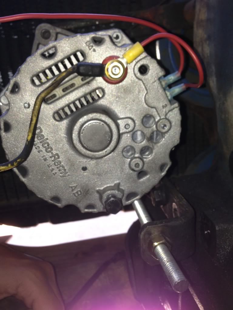
Okay start by removing the bolt on top of the red terminal connected to your alternator.
Now your original generator had a thick yellow wire connected to it, along with 2 small black ones. Connect that thick yellow wired to the red terminal on the alternator.
Cut a 3 inch peice of 12 gauge wire and connect a "o" shaped terminal to one side and a female socket terminal to the other. Connect the "o" shaped terminal to the same red terminal you connected that yellow wire to. You can now tighten that bolt down. Look at picture 2 it illustrates it pretty clearly.
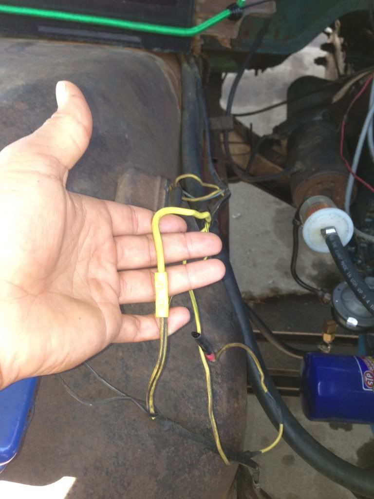
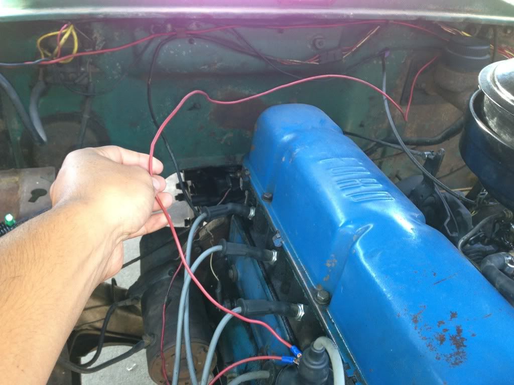
Now trace that yellow wire to the voltage regulator and mark it. Now from the voltage regulator trace the charging wire for the battery back to the starting relay (it is also a thick yellow wire). You can see the starting relay with a bunch of wires connected to it near to the left of my hand in picture 3. Now mark it.
Once you have found both wires snip both ends that connected to the voltage regulator and proceed to connect them using a crimp sleeve.
shown in picture 1.
Now for the last part take about 4 feet (if too long cut to length) of 12 gauge wire and connect one "o" shaped terminal to one side and a female socket style terminal to the other. Take the "o" shaped terminal side and connected it the back of the ignition coil (closest to cab) and connect the female socket style terminal to the left (looking at the back of the alternator) male connector on the alternator. Right next that other wire that you've already connected. Shown in picture 2.
Closer to the alternator you want to splice in a diode in that last wire in the previous step. If you don't you'll be like me and your truck will continue run with key removed.
I'll update this step once I do it myself.
I hope this helped! If you need me to explain anything further don't hesitate to ask.
- John
Okay now for the wiring part
its quite simple actually,
Things you'll need:
wire cutters/strippers
assorted wire terminals
12 volt diode
a roll of 12 gauge red wire
volt meter
1.
2.
3.
Okay start by removing the bolt on top of the red terminal connected to your alternator.
Now your original generator had a thick yellow wire connected to it, along with 2 small black ones. Connect that thick yellow wired to the red terminal on the alternator.
Cut a 3 inch peice of 12 gauge wire and connect a "o" shaped terminal to one side and a female socket terminal to the other. Connect the "o" shaped terminal to the same red terminal you connected that yellow wire to. You can now tighten that bolt down. Look at picture 2 it illustrates it pretty clearly.
Now trace that yellow wire to the voltage regulator and mark it. Now from the voltage regulator trace the charging wire for the battery back to the starting relay (it is also a thick yellow wire). You can see the starting relay with a bunch of wires connected to it near to the left of my hand in picture 3. Now mark it.
Once you have found both wires snip both ends that connected to the voltage regulator and proceed to connect them using a crimp sleeve.
shown in picture 1.
Now for the last part take about 4 feet (if too long cut to length) of 12 gauge wire and connect one "o" shaped terminal to one side and a female socket style terminal to the other. Take the "o" shaped terminal side and connected it the back of the ignition coil (closest to cab) and connect the female socket style terminal to the left (looking at the back of the alternator) male connector on the alternator. Right next that other wire that you've already connected. Shown in picture 2.
Closer to the alternator you want to splice in a diode in that last wire in the previous step. If you don't you'll be like me and your truck will continue run with key removed.
I'll update this step once I do it myself.
I hope this helped! If you need me to explain anything further don't hesitate to ask.
- John
Last edited by JohnDigger; 08-20-2013 at 03:58 PM. Reason: Added numbers to pictures.

#4
08-23-2013, 12:59 AM

#5
10-16-2013, 12:30 PM
#6
10-16-2013, 09:11 PM
Logistics Pro
#7
10-16-2013, 09:22 PM
Trending Topics
#8
10-16-2013, 09:51 PM

#10
05-26-2014, 12:01 PM

-Wiring Setup -
Okay now for the wiring part
its quite simple actually,
Things you'll need:
wire cutters/strippers
assorted wire terminals
12 volt diode
a roll of 12 gauge red wire
volt meter
1.
2.
3.
Okay start by removing the bolt on top of the red terminal connected to your alternator.
Now your original generator had a thick yellow wire connected to it, along with 2 small black ones. Connect that thick yellow wired to the red terminal on the alternator.
Cut a 3 inch peice of 12 gauge wire and connect a "o" shaped terminal to one side and a female socket terminal to the other. Connect the "o" shaped terminal to the same red terminal you connected that yellow wire to. You can now tighten that bolt down. Look at picture 2 it illustrates it pretty clearly.
Now trace that yellow wire to the voltage regulator and mark it. Now from the voltage regulator trace the charging wire for the battery back to the starting relay (it is also a thick yellow wire). You can see the starting relay with a bunch of wires connected to it near to the left of my hand in picture 3. Now mark it.
Once you have found both wires snip both ends that connected to the voltage regulator and proceed to connect them using a crimp sleeve.
shown in picture 1.
Now for the last part take about 4 feet (if too long cut to length) of 12 gauge wire and connect one "o" shaped terminal to one side and a female socket style terminal to the other. Take the "o" shaped terminal side and connected it the back of the ignition coil (closest to cab) and connect the female socket style terminal to the left (looking at the back of the alternator) male connector on the alternator. Right next that other wire that you've already connected. Shown in picture 2.
Closer to the alternator you want to splice in a diode in that last wire in the previous step. If you don't you'll be like me and your truck will continue run with key removed.
I'll update this step once I do it myself.
I hope this helped! If you need me to explain anything further don't hesitate to ask.
- John
This was a great write up. I did a similar swap to my pickup yesterday. I'm just wondering what type of diode you used. My local parts guy was of no help. Thanks for any help

Thread
Thread Starter
Forum
Replies
Last Post
51PanelMan
1948 - 1956 F1, F100 & Larger F-Series Trucks
10
04-15-2013 07:06 PM
52' fordnut
1980 - 1986 Bullnose F100, F150 & Larger F-Series Trucks
4
12-01-2012 11:51 PM