1985 F250 5.8L wiring diagrams and fuse box diagram
#16
Glad I can help. It started more as a Chrysler Turbo resource, then as I got redoing my truck, and more involved with FTE, sort of morphed into a Ford resource.
#17
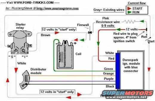
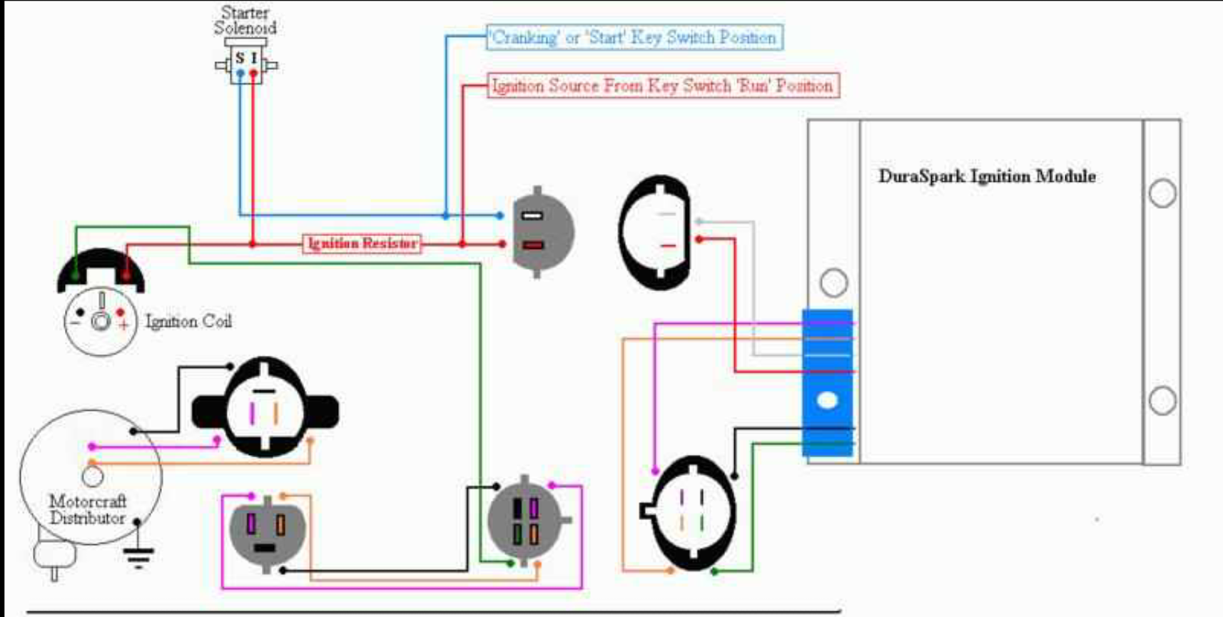
Today I tried to rewire the DSII box well just the 2 wire plug coming out of the box is one red and one white wire and then at the plug they switch? I noticed that the starting relay didnt have anything hooked to the "I" terminal. So I rewired the "I" to the positive on the coil then a inline resistor the to the red wire on the DSII 2 wire plug. Once I energized the relay turning the key even off it wouldn't stop cranking.
#18
If you noticed on the DS-II diagram, the wires do reverse at the plug. The "I" terminal is only used on 7.5L with the hot fuel handling package. It provides priming power to the in-tank pump(s). The white with light blue dots wire is only hot in run, it goes the the red wire on the DS-II box. The red with light blue stripe they show in the diagram actually doesn't exist on a DS-II box, it would be the middle pin on the 3 pin plug. The start circuit red with light blue goes to the white DS-II wire in that plug. The resistor is between pin I1 and I2 on the ignition switch, I1 is run, I2 is start bypass. It will backfeed to the red DS-II wire, but the white wire is the critical one, it activates the cranking retard capability of the DS-II module.
The reason it won't stop cranking, you are activating the starter relay from the ignition power, however, stuck Chinese starter relays are very common.
The reason it won't stop cranking, you are activating the starter relay from the ignition power, however, stuck Chinese starter relays are very common.
#19
If you noticed on the DS-II diagram, the wires do reverse at the plug. The "I" terminal is only used on 7.5L with the hot fuel handling package. It provides priming power to the in-tank pump(s). The white with light blue dots wire is only hot in run, it goes the the red wire on the DS-II box. The red with light blue stripe they show in the diagram actually doesn't exist on a DS-II box, it would be the middle pin on the 3 pin plug. The start circuit red with light blue goes to the white DS-II wire in that plug. The resistor is between pin I1 and I2 on the ignition switch, I1 is run, I2 is start bypass. It will backfeed to the red DS-II wire, but the white wire is the critical one, it activates the cranking retard capability of the DS-II module.
The reason it won't stop cranking, you are activating the starter relay from the ignition power, however, stuck Chinese starter relays are very common.
The reason it won't stop cranking, you are activating the starter relay from the ignition power, however, stuck Chinese starter relays are very common.
#20
Ok, take a close look at the charging system diagrams. The original system on these trucks is very strange. If you have an ammeter (useless at best) there is a special piece of wire that is calibrated for the shunt ammeter. The other issue, everything on the truck except the starter is actually fed from the alternator harness. Until the alternator starts charging, power flow is from the battery, through the fusible link into the alternator harness. From there it fans out through more fusible links to the inside of the cab. From what you describe, either your ignition module may be failing or voltage to the system is either too high, or more likely too low. Other issue can be, coil failing, pickup in distributor failing.
#21
Ok, take a close look at the charging system diagrams. The original system on these trucks is very strange. If you have an ammeter (useless at best) there is a special piece of wire that is calibrated for the shunt ammeter. The other issue, everything on the truck except the starter is actually fed from the alternator harness. Until the alternator starts charging, power flow is from the battery, through the fusible link into the alternator harness. From there it fans out through more fusible links to the inside of the cab. From what you describe, either your ignition module may be failing or voltage to the system is either too high, or more likely too low. Other issue can be, coil failing, pickup in distributor failing.
The "special piece of wire that is calibrated for the shunt ammeter." That you spoke of is that resistor on the engine side of the fire wall or the passenger side of the firewall?
So far I have replaced the distributor [and cap and rotor], coil, wires and have a spare DSII box.
I checked the primary and secondary resistance on the coil they were within specs. Then I plugged in a test light [an inline type that replaces the plug wire] between the coil and the distributor cap. A yellow fant spark was displayed on the test light.
What would be the best way to test those open ended wires?
#23
If you noticed on the DS-II diagram, the wires do reverse at the plug. The "I" terminal is only used on 7.5L with the hot fuel handling package. It provides priming power to the in-tank pump(s). The white with light blue dots wire is only hot in run, it goes the the red wire on the DS-II box. The red with light blue stripe they show in the diagram actually doesn't exist on a DS-II box, it would be the middle pin on the 3 pin plug. The start circuit red with light blue goes to the white DS-II wire in that plug. The resistor is between pin I1 and I2 on the ignition switch, I1 is run, I2 is start bypass. It will backfeed to the red DS-II wire, but the white wire is the critical one, it activates the cranking retard capability of the DS-II module.
The reason it won't stop cranking, you are activating the starter relay from the ignition power, however, stuck Chinese starter relays are very common.
The reason it won't stop cranking, you are activating the starter relay from the ignition power, however, stuck Chinese starter relays are very common.
#24
First, don't even try to do wiring using a cell phone screen. Second, look at the charging circuit diagram, first the diesel one, then go from that to what you have now. The shunt wire is the special wire, but if in your disconnected wires on the right side you can identify a red with orange and yellow with light green those would be the ammeter wires.
The purple may have started life as red.
You might be ahead of the game if you can find a gas engine truck in a junkyard that has a good front harness and get the whole thing. It won't be fun, but it might be easier and faster for you.
The purple may have started life as red.
You might be ahead of the game if you can find a gas engine truck in a junkyard that has a good front harness and get the whole thing. It won't be fun, but it might be easier and faster for you.
#25
First, don't even try to do wiring using a cell phone screen. Second, look at the charging circuit diagram, first the diesel one, then go from that to what you have now. The shunt wire is the special wire, but if in your disconnected wires on the right side you can identify a red with orange and yellow with light green those would be the ammeter wires.
The purple may have started life as red.
You might be ahead of the game if you can find a gas engine truck in a junkyard that has a good front harness and get the whole thing. It won't be fun, but it might be easier and faster for you.
The purple may have started life as red.
You might be ahead of the game if you can find a gas engine truck in a junkyard that has a good front harness and get the whole thing. It won't be fun, but it might be easier and faster for you.
#27
#28
So i pulled the diesel harness out and am in the process of installing a 1980 ford harness in the 1985 chassis.
Trying to follow the haynes wiring diagram i ran in to a snag.
With in the key are "diesel" "option" and "GA only" could you please shed some light on what "GA only" could be?
#29
GA I would assume is gas, but I have never trusted a Haynes manual on wiring. They try to cover too much in a small area.
1980 harness is way different on the alternator, 1980 had the 1G (external regulator) system. I can't help you much on a 1980, my AllData only covers back to 1983 in detail, 1982 partially.
1980 harness is way different on the alternator, 1980 had the 1G (external regulator) system. I can't help you much on a 1980, my AllData only covers back to 1983 in detail, 1982 partially.
#30
GA I would assume is gas, but I have never trusted a Haynes manual on wiring. They try to cover too much in a small area.
1980 harness is way different on the alternator, 1980 had the 1G (external regulator) system. I can't help you much on a 1980, my AllData only covers back to 1983 in detail, 1982 partially.
1980 harness is way different on the alternator, 1980 had the 1G (external regulator) system. I can't help you much on a 1980, my AllData only covers back to 1983 in detail, 1982 partially.
I canned the 1G alternator and upgraded to a 3G alternator some time ago.
After 6 days on this project i got the engine to turn over yesterday. I still have to figure out a start run wire to tap into for the fuel pump relay and i have found a unidentified 2 wire plug under the drivers side frame rail.
Thanks again for your help and time, Jon


