98 Ranger IFS Swap.
#1
 04-27-2013, 04:10 PM

Join Date: Jan 2013
Location: NW Ohio
Posts: 317
Likes: 0
Received 0 Likes
on
0 Posts
98 Ranger IFS Swap.
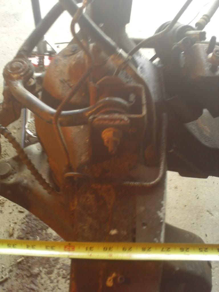
I figure its best to start this thread with the primary reason I chose this clip swap. The ford body builders guide listed the 98 ranger chassis at 32.4 inches wide( outside to outside) . After crawling under a ranger, the frame at the rear of the lower control arm measures 32inches wide exactly. Which will be the perfect width for the 49 f1 32 inch frame width.
O photo bucket is making me angry
The tape is crooked I was holding a trouble light and the tape.

O photo bucket is making me angry
The tape is crooked I was holding a trouble light and the tape.
#2
04-27-2013, 09:49 PM
Elder User
Join Date: Feb 2012
Location: Central Oregon
Posts: 948
Likes: 0
Received 0 Likes
on
0 Posts
#3
04-27-2013, 10:03 PM
Join Date: Jan 2013
Location: NW Ohio
Posts: 317
Likes: 0
Received 0 Likes
on
0 Posts
#4
04-28-2013, 01:32 PM
Join Date: Jan 2013
Location: NW Ohio
Posts: 317
Likes: 0
Received 0 Likes
on
0 Posts
Havent gotten much done today. Been fighting this ranger chassis trying to get it level. There is one flat level spot on the frame back by the bed. Between that an the underside of the crossmember they are both off about 1 degree. A little more shimming an both should be level. Im questioning if this is correct or not because the engine mounts now have a 4 degree slope to the rear. The lower arms have no good place to measure an angle. They dont even look demensionally square in any way. I may have to track down a 98 ranger with an engine in it to get an angle off its crossmember.
#5
04-28-2013, 01:56 PM
Fleet Owner
#6
04-28-2013, 10:00 PM
Join Date: Jan 2013
Location: NW Ohio
Posts: 317
Likes: 0
Received 0 Likes
on
0 Posts
Agreed Alby. After a few more hours of doing the mind numbing task of shim and measure everything...repeat. I now have 3 horizontal portions of the chassis at 0 degrees. The tophat for the coil-through shocks rests at about 3 degrees. The crossmember underneath is on zero, just not centered. engine mounts are just over 4 degrees. Front to rear (z axis) is about as level as i think i can get it. The left/ right axis (x axis) rest on the 0 degree mark for all the cross braces/tranny crossmember. With the multiple point across the length of the chassis that are coming out to level, I can only assume this is the proper orientation. At this point the control arm "look good" from an eyeball perspective.
#7
04-28-2013, 10:37 PM

Trending Topics
#8
04-28-2013, 10:42 PM
Join Date: Jan 2013
Location: NW Ohio
Posts: 317
Likes: 0
Received 0 Likes
on
0 Posts
#9
04-28-2013, 11:10 PM
Since your using a frame clip all the factory geometry will be intact so the main issue is just making sure it is welded in straight. With the cams, you'll have about 2 degrees of total adjustment available. To even get a proper reading, you will need the truck full assembled and have camber and toe within .5 of a degree of what you want.
I assume you don't have access to an alignment machine so you would have to get an old magnetic alignment bubble gauge and be able to turn the wheel to 20 degrees. There are several steps but I've only ever used computerized wheel aligners so I can't quite explain the proper way.
I assume you don't have access to an alignment machine so you would have to get an old magnetic alignment bubble gauge and be able to turn the wheel to 20 degrees. There are several steps but I've only ever used computerized wheel aligners so I can't quite explain the proper way.
#10
04-29-2013, 06:46 AM
Join Date: Jan 2013
Location: NW Ohio
Posts: 317
Likes: 0
Received 0 Likes
on
0 Posts
I wasnt so much worried about correct caster just being close. More for a peace of mind thing, letting me know im on the right track. The local hotrod shop in Ottawa ( ohio not canada) did a 99 frame swap for someone and it gets stored up there as well. Might have to slip up there today and take the angle finder to see how the underside of that crossmember sits.
#11
04-29-2013, 03:27 PM
Join Date: Jan 2013
Location: NW Ohio
Posts: 317
Likes: 0
Received 0 Likes
on
0 Posts
Stopped up at the shop today. Nick the builder suggested putting it back on all 4 wheels and matching the measurements. so I dropped the frame back down. The flat spots are canted towards the rear 1/2 a degree. And the top hat is at a 2.5 degree angle. crossmember sits at 1+ degree to the front. These measurements are very near the ones when I was trying to prop and get the frame level. Why oh why did I not do this earlier.
#12
05-01-2013, 08:07 AM
Join Date: Jan 2013
Location: NW Ohio
Posts: 317
Likes: 0
Received 0 Likes
on
0 Posts
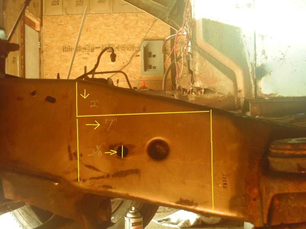
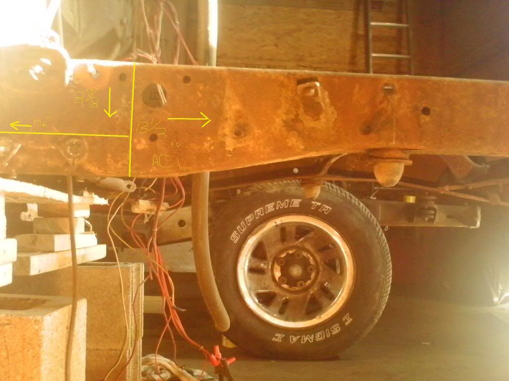
Got some pics for everyone today. I have my cut lines for both chassis made. The F1 is propped up and level the 98 Ranger rolling chassis sits on its 4 wheels. The lines in the pictures do not look straight because I overlapped them with MS paint with a fat pointer font. It should give you all a clear image of what I am doing. All the vertical and horizontal lines on both chassis were made with a carpenters square AND a round angle finder. Verticals read 0 and horizontals reading 90. Yes the ranger chassis in on the ground, but the purpose is to make lines using gravity as a constant. This will make the IFS crossmember at near exactly the same angle on the f1 frame as its sits on the ranger frame. The f1 frame will be a rolling chassis when swap is complete.
Ranger lines:
Ranger lines:
#13
05-01-2013, 08:09 AM
Join Date: Jan 2013
Location: NW Ohio
Posts: 317
Likes: 0
Received 0 Likes
on
0 Posts
#14
05-01-2013, 08:11 AM
Join Date: Jan 2013
Location: NW Ohio
Posts: 317
Likes: 0
Received 0 Likes
on
0 Posts

#15
05-01-2013, 08:19 AM
Join Date: Jan 2013
Location: NW Ohio
Posts: 317
Likes: 0
Received 0 Likes
on
0 Posts
I put a 1/78 drop. This will keep me close to stock ride height. Should anyone want the 2 inch drop from the ranger chassis, they could adjust it back up. Or if you are really ***** nilly it couldbe dropped another 2 inches. there will be approxamately 3 inches of ranger chassis under the F1 chassis. The Ranger chassis actually goes down so technically you could run its frame back 2 feet should it be deemed needed. the seven inch horizontal line was easy the 2 humps for the spring hanger are level. 7 inches will take the ranger frame back past the spring hanger. this is where I will cut it and do triangle boxing upto the F1 frame. 7inches of bead weld horizontal should be a darn good hold. Up on the top as well there will be triangulated box going from the cut out F1 down to the upper control arm mounts. alignment bolts.