
Project Rednecktified
#61
 03-14-2013, 11:29 AM


Join Date: Sep 2012
Posts: 220
Likes: 0
Received 0 Likes
on
0 Posts
#62
04-05-2013, 08:21 AM
Join Date: Sep 2012
Posts: 220
Likes: 0
Received 0 Likes
on
0 Posts
Good morning all! Sorry I haven�t updated in a while, it�s been busy here! Some good progress though.
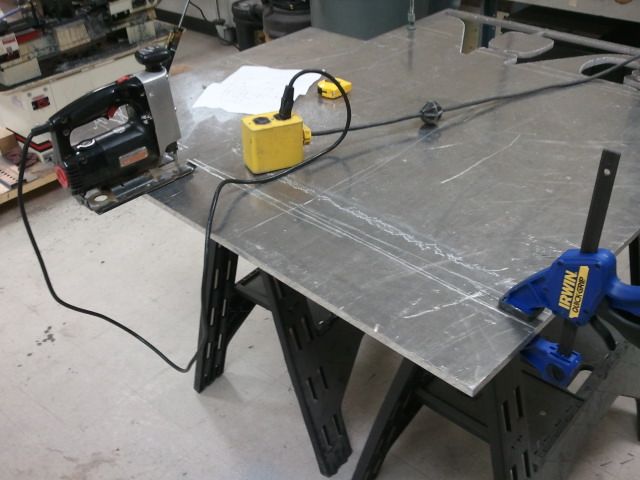
Started on the tappet cover last week. Took me like an hour to cut this out with a jig saw. �� aluminum plate.
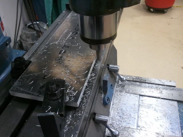
On the mill. Squared up the edges, and drilled the mounting holes.
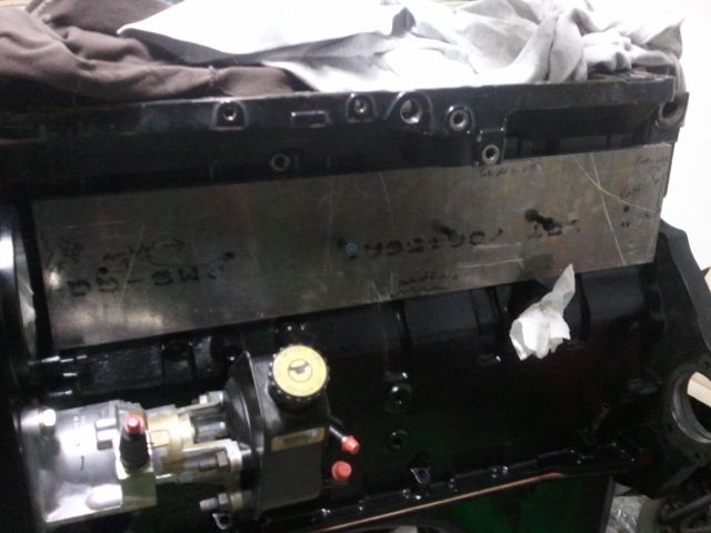
Test fit! The holes are off just a tad. Bad measurements on my part. No big deal, I made the holes tight anyway. You�ve prolly noticed that there are some deep scratches in the plate. I�m going to take a fly cutter to both sides to clean it up once I get the machining done.
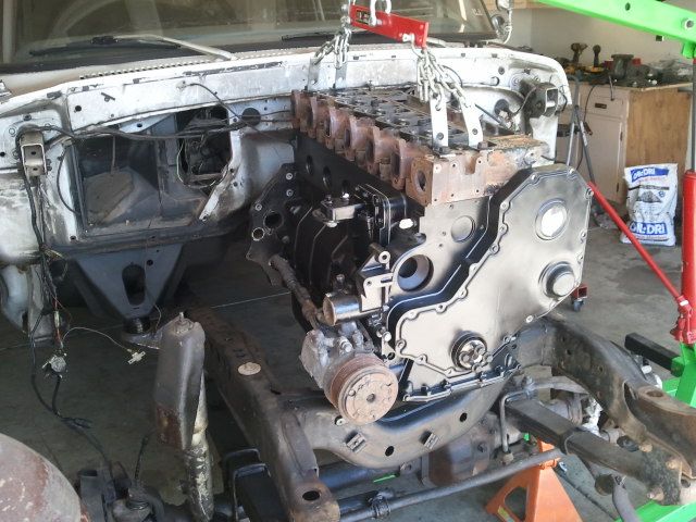
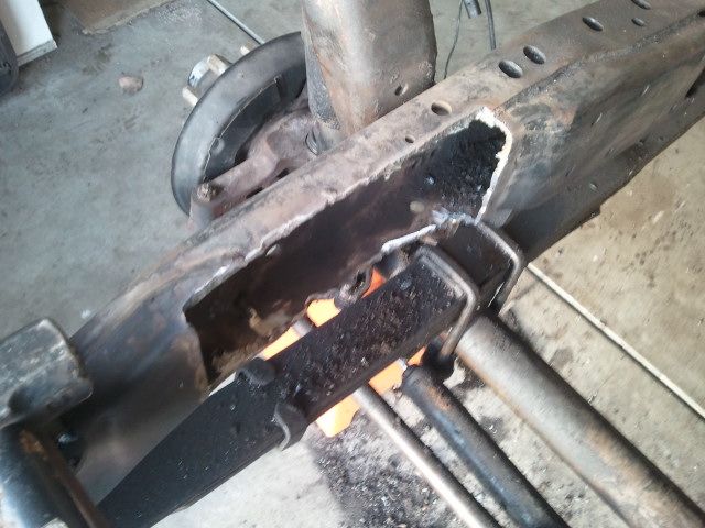
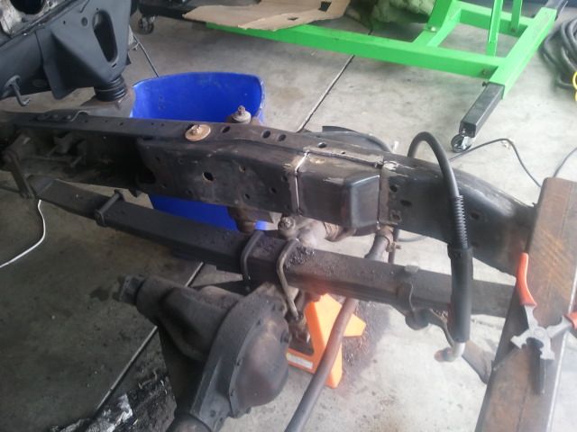
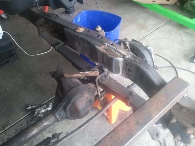
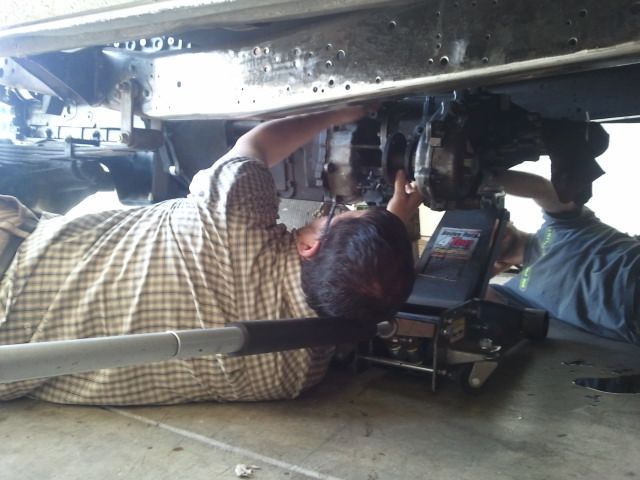
Oh my gerd! Test fitting the engine. That ugly azz cross member is in the way of the AC pump.
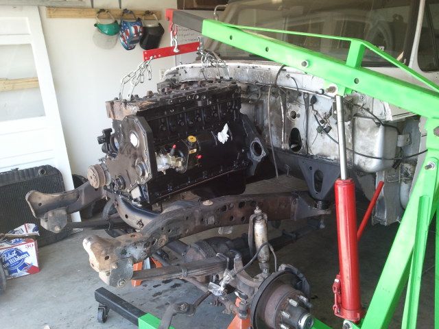
Needs to be lowered in this position. You can see where the AC compressor hits the cross member.
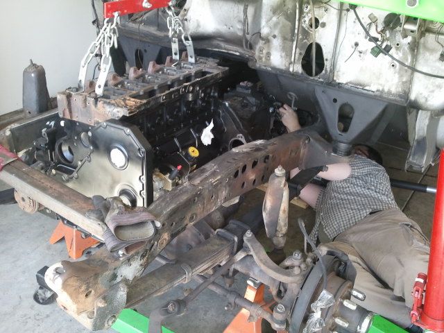
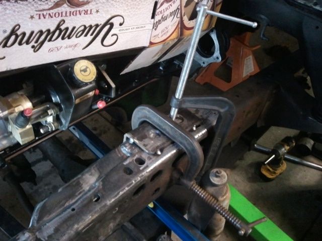
Easy fix! Put a piece of tube to support the frame temporarily, and cut that thing out.
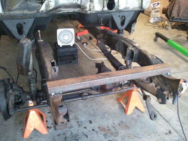
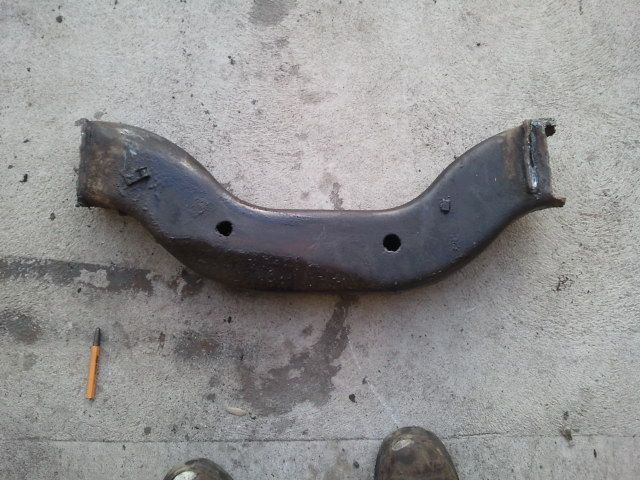
This is an ugly piece of engineering! Its basically 2 pieces of bent C channel welded together.
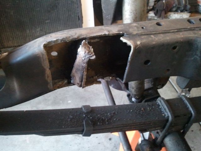
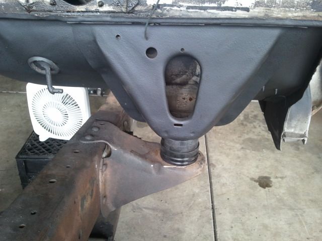
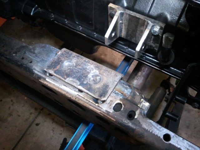
Final clearance for the AC compressor. This will be plated after I make the motor mounts. There will be about a �� of clearance between the Compressor and the frame.
I don�t have a pic of it, but on these old dentsides the engines are offset to the passenger side, so the transmission tunnel on the cab is offset to the passenger side. The cummins will be offset to the passenger side about 1.5� if I remember correctly. This should give me enough clearance for the tranny, etc. More on that after this weekend, I�m hoping to mock up the whole driveline and build some motor mounts!
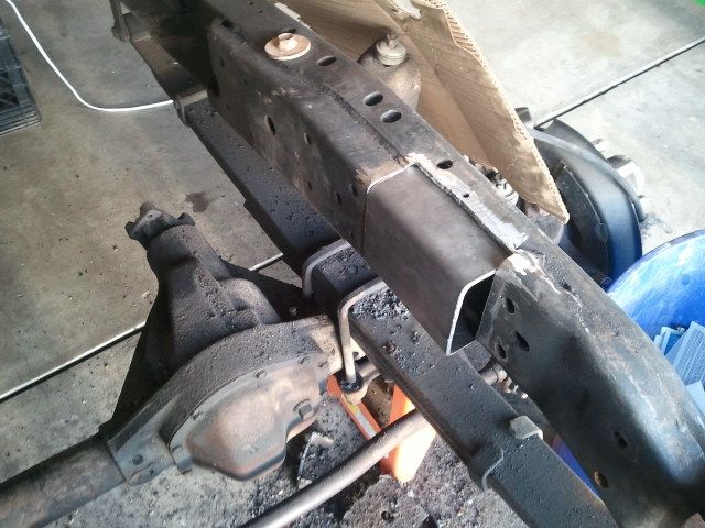
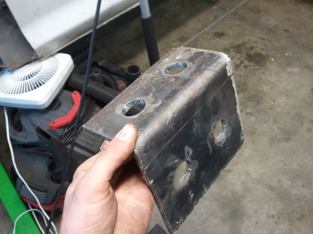
Had Aaron at Brucker Brothers in Longmont bend me up a piece of 3/16� plate to fill the �cross-member hole� on the drivers side. Shout out to this guy! He does great work, and just a good guy overall. If you need some metal fab work of any kind look him up.
And that reminds me, I need to buy one of these:
So I decided that abrupt right angle in the piece was going to look like crap, so I put a 45 degree cut on it, and filled it with plate. I should have this welded in this weekend.
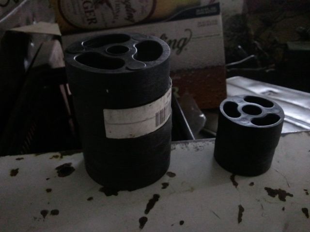
Instead of welding that piece in, I decided to have one of these! Ok, its puzzle time! Can you spot what is different in this picture (other than the seats in the bed). HINT: you might want to check the earlier photos of the truck from behind.
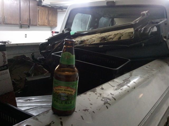
1� bodylift pucks!
Took a trip down to Maxtorq last week and picked up the rest of the gaskets for the Cummins. He should have my Turbo done next week too. He�s taking a used HX35 and putting new blade wheel in it, along with a total rebuild. WAY cheaper than a brand new aftermarket piece, plus he�s building me a custom wastegate.
I�ll be on vacation next week. Me and some friends are taking the quads to Moab. Gonna be a BLAST!!
Started on the tappet cover last week. Took me like an hour to cut this out with a jig saw. �� aluminum plate.
On the mill. Squared up the edges, and drilled the mounting holes.
Test fit! The holes are off just a tad. Bad measurements on my part. No big deal, I made the holes tight anyway. You�ve prolly noticed that there are some deep scratches in the plate. I�m going to take a fly cutter to both sides to clean it up once I get the machining done.
Oh my gerd! Test fitting the engine. That ugly azz cross member is in the way of the AC pump.
Needs to be lowered in this position. You can see where the AC compressor hits the cross member.
Easy fix! Put a piece of tube to support the frame temporarily, and cut that thing out.
This is an ugly piece of engineering! Its basically 2 pieces of bent C channel welded together.
Final clearance for the AC compressor. This will be plated after I make the motor mounts. There will be about a �� of clearance between the Compressor and the frame.
I don�t have a pic of it, but on these old dentsides the engines are offset to the passenger side, so the transmission tunnel on the cab is offset to the passenger side. The cummins will be offset to the passenger side about 1.5� if I remember correctly. This should give me enough clearance for the tranny, etc. More on that after this weekend, I�m hoping to mock up the whole driveline and build some motor mounts!
Had Aaron at Brucker Brothers in Longmont bend me up a piece of 3/16� plate to fill the �cross-member hole� on the drivers side. Shout out to this guy! He does great work, and just a good guy overall. If you need some metal fab work of any kind look him up.
And that reminds me, I need to buy one of these:
So I decided that abrupt right angle in the piece was going to look like crap, so I put a 45 degree cut on it, and filled it with plate. I should have this welded in this weekend.
Instead of welding that piece in, I decided to have one of these! Ok, its puzzle time! Can you spot what is different in this picture (other than the seats in the bed). HINT: you might want to check the earlier photos of the truck from behind.
1� bodylift pucks!
Took a trip down to Maxtorq last week and picked up the rest of the gaskets for the Cummins. He should have my Turbo done next week too. He�s taking a used HX35 and putting new blade wheel in it, along with a total rebuild. WAY cheaper than a brand new aftermarket piece, plus he�s building me a custom wastegate.
I�ll be on vacation next week. Me and some friends are taking the quads to Moab. Gonna be a BLAST!!

#65
04-05-2013, 12:00 PM
Join Date: Sep 2012
Posts: 220
Likes: 0
Received 0 Likes
on
0 Posts
#67
04-05-2013, 12:14 PM

#68
04-05-2013, 12:40 PM
Join Date: Sep 2012
Posts: 220
Likes: 0
Received 0 Likes
on
0 Posts
#69
04-05-2013, 01:51 PM
#70
04-05-2013, 01:56 PM

#71
04-06-2013, 06:46 PM
Join Date: Sep 2012
Posts: 220
Likes: 0
Received 0 Likes
on
0 Posts
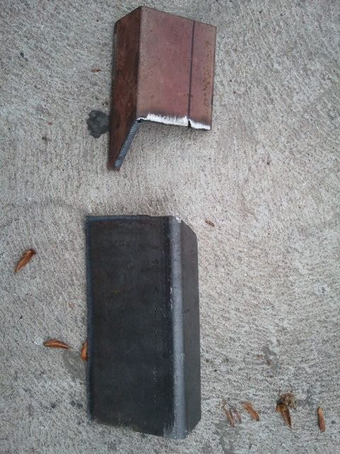
Ok, short little update here. Got the patch welded in for the drivers side hole in the frame from ripping out the cross member.
Tacked in place:
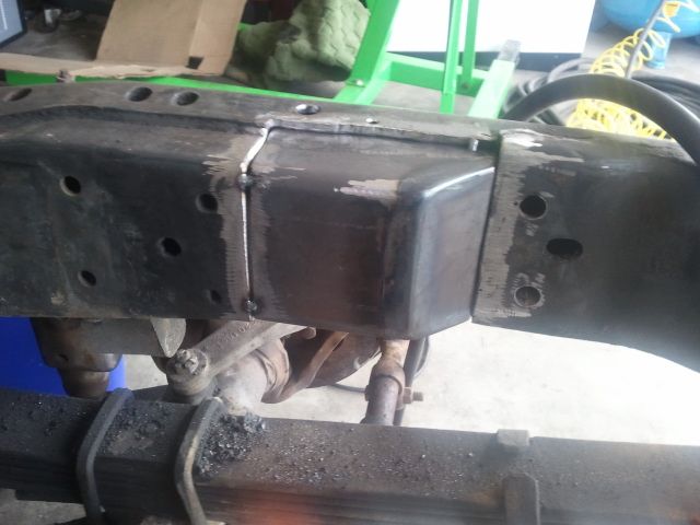
Weld ****! The weld isn't straight because the cut wasn't straight. So sue me, the factory frame was goobered alot worse.
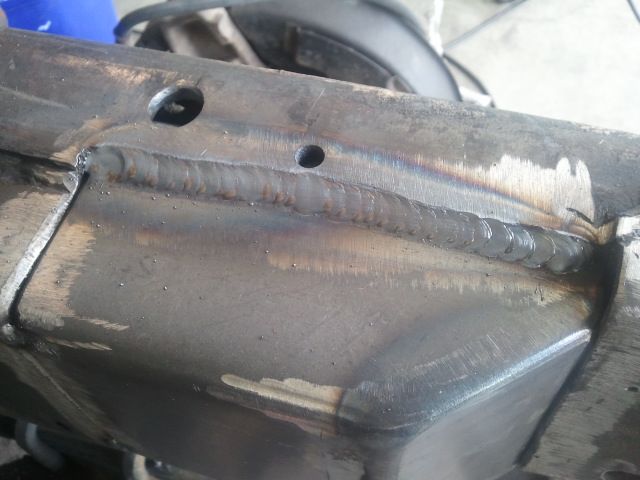
Almost looks like it came like that!
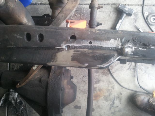
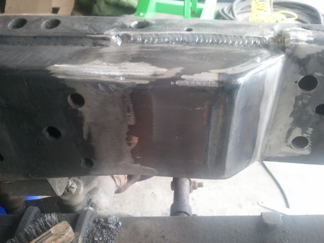
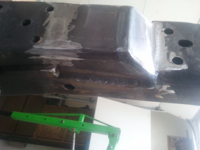
Underside:
Got the body pucks in!
Hoping to patch the passenger side frame tonight or tomorrow. Then I gotta get ready for vacation! Yeeeehhhhhaawwwwwwwwwww!!! Cya next week ya'll!
Tacked in place:
Weld ****! The weld isn't straight because the cut wasn't straight. So sue me, the factory frame was goobered alot worse.
Almost looks like it came like that!
Underside:
Got the body pucks in!
Hoping to patch the passenger side frame tonight or tomorrow. Then I gotta get ready for vacation! Yeeeehhhhhaawwwwwwwwwww!!! Cya next week ya'll!
#72
04-08-2013, 07:31 PM
Lead Driver
Looking good! I like the replacement for the cut out area of the cross member. I WISH I would have cut mine out & made a removable one vs. cutting down the stock cross member like I did. Oh well..
As for this:
Just make one - you've got the skills.
I made my own & it works great

As for this:
Just make one - you've got the skills.
I made my own & it works great
#73
05-06-2013, 05:46 PM
Join Date: Sep 2012
Posts: 220
Likes: 0
Received 0 Likes
on
0 Posts
Hey all! Yes, I�m still alive. Got quite a bit of progress done the last few weeks.
Made the Motor Mounts. They warped a little when I welded them, so I machined the bottom mounting surface flat. I also machined into the welds where the bolts go so they can sit flush.
Got the driveline in place. Had some help. Big thanks to Mark and Rueben again!
Lowered the engine wayyyy down to bolt the transmission on.
When we were going to bolt the tranny onto the engine, we noticed that the flywheel housing wasn�t �thick� enough. Turns out that I need a 94� or newer flywheel housing. Nothing that money can�t fix!
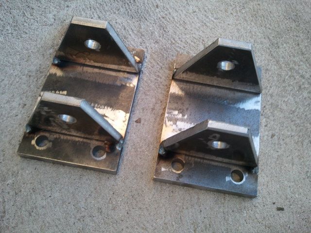
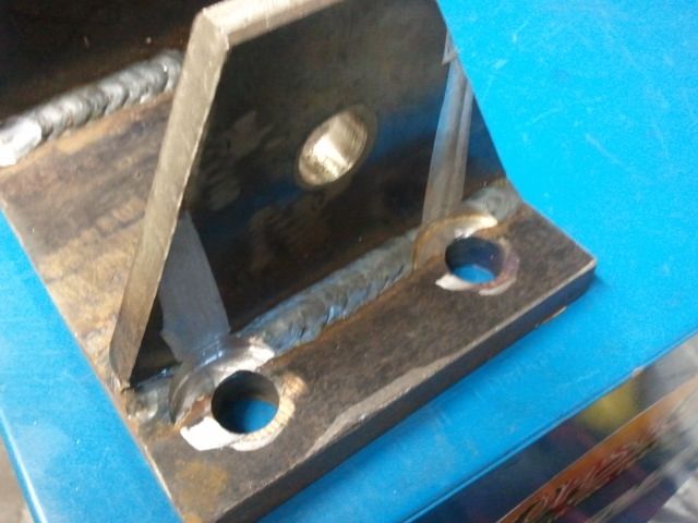
Made some gusset plates for the engine mounts, with holes cut to fill with weld for more weld surface area.
All tackered in place
Made the Motor Mounts. They warped a little when I welded them, so I machined the bottom mounting surface flat. I also machined into the welds where the bolts go so they can sit flush.


Got the driveline in place. Had some help. Big thanks to Mark and Rueben again!

Lowered the engine wayyyy down to bolt the transmission on.

When we were going to bolt the tranny onto the engine, we noticed that the flywheel housing wasn�t �thick� enough. Turns out that I need a 94� or newer flywheel housing. Nothing that money can�t fix!
Made some gusset plates for the engine mounts, with holes cut to fill with weld for more weld surface area.


All tackered in place

#74
05-06-2013, 05:54 PM
Join Date: Sep 2012
Posts: 220
Likes: 0
Received 0 Likes
on
0 Posts
�Merica.
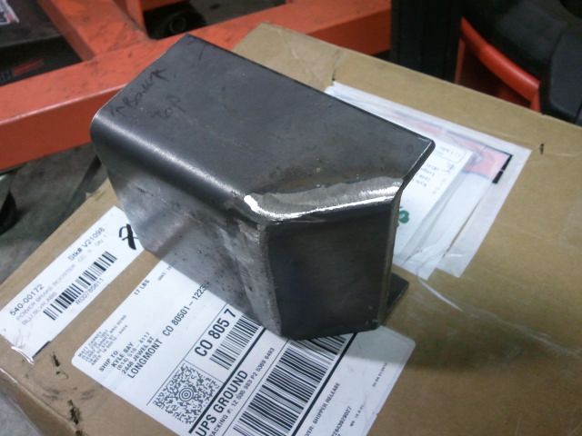
Started on the engine cradle cross member. Making it out of 1.75x.120 DOM tubing, with guessets at each end. Thoughts on this? Will it be strong enough? I�m having thoughts, but I�m an overkill fanatic!
Going to weld the tubing to these plates, then these plates to the frame. More steel=stronger!
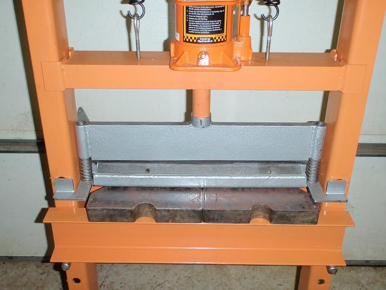
Been a while since I busted this thing out. Time to have some fun!
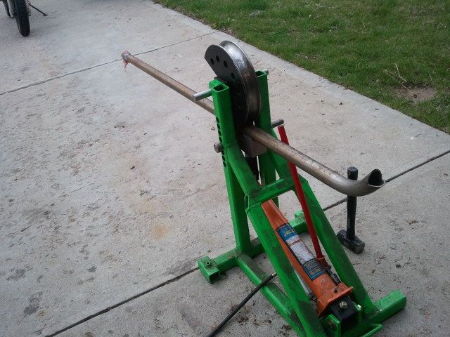
So because of the nature of the bends and the placement, I had to do some math to figure out bend angles and bend placements.
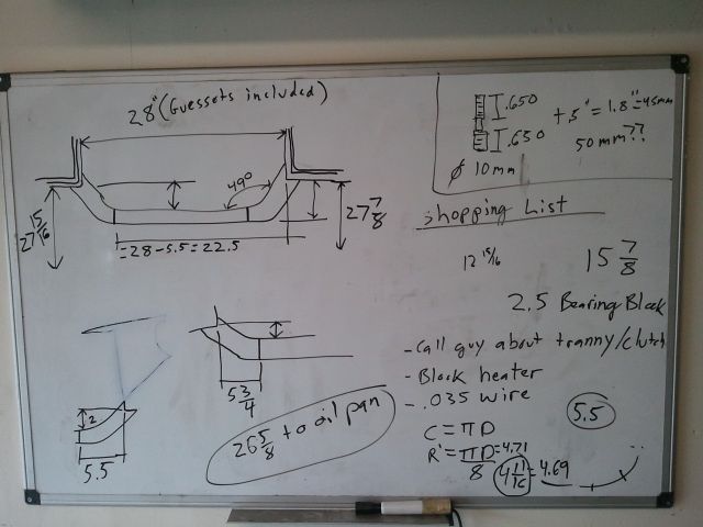
Got it pretty darn close. Not perfect, but at $6/foot it�ll work!
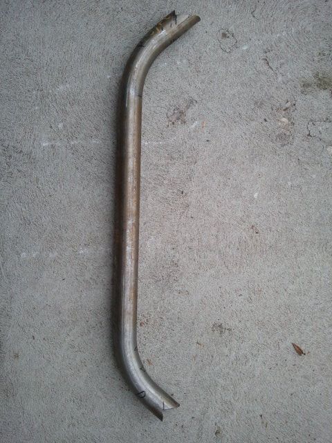
Should have that X-member done this week. Then going to build the tranny X-member, which will also be made from 1.75x1.20 DOM, and will use bushings on either end (same bushings as motor mounts).
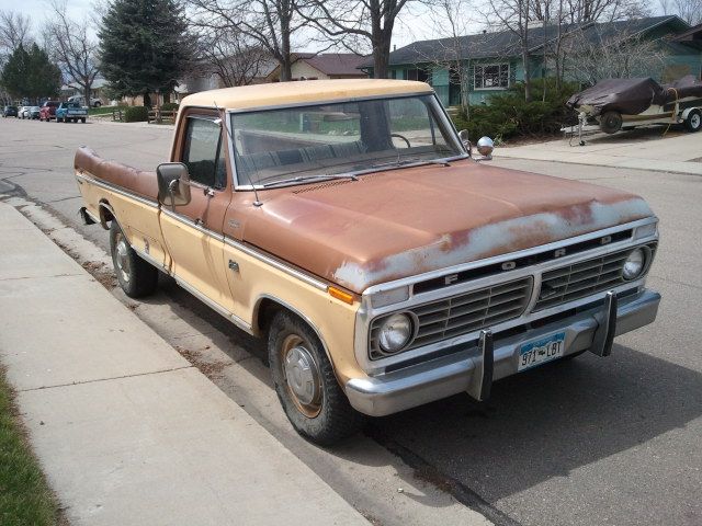
Oh, and picked this gem up the other day. Got a steal on it so couldn�t pass it up! (and yes it runs!). It'll be parted out, and transfer the title to the Crew so I don't have to do emissions.

Started on the engine cradle cross member. Making it out of 1.75x.120 DOM tubing, with guessets at each end. Thoughts on this? Will it be strong enough? I�m having thoughts, but I�m an overkill fanatic!
Going to weld the tubing to these plates, then these plates to the frame. More steel=stronger!

Been a while since I busted this thing out. Time to have some fun!

So because of the nature of the bends and the placement, I had to do some math to figure out bend angles and bend placements.

Got it pretty darn close. Not perfect, but at $6/foot it�ll work!

Should have that X-member done this week. Then going to build the tranny X-member, which will also be made from 1.75x1.20 DOM, and will use bushings on either end (same bushings as motor mounts).
Oh, and picked this gem up the other day. Got a steal on it so couldn�t pass it up! (and yes it runs!). It'll be parted out, and transfer the title to the Crew so I don't have to do emissions.

#75
05-06-2013, 06:47 PM
Lead Driver
More steel = more weight. The strength is in the design...
As for the design - run tubes up to catch the TOP (or upper level) of the frame as well. There was a reason the factory caught the entire vertical face of the frame rails - they'll try & fold inward toward the CL of the truck if you don't. Especially with the weight and torque of the cummins.

