3G alternator wiring clarification
#1
 09-10-2012, 02:22 AM


Join Date: Aug 2011
Location: Round Rock, TX
Posts: 230
Likes: 0
Received 0 Likes
on
0 Posts
3G alternator wiring clarification
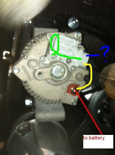
I have a 95amp 3G alternator mounted, from a F150/Bronco. The wiring threads I've been reading have confused me. Hopefully someone can make this simple for me.
On the internal regulator terminals they are labeled as: A, S, I.
A - gets connected to the terminal that will be connected directly to the battery using an 8 gauge piece of wire, to charge the batt. (yellow line in pic)
S - Gets connected to one of the screws that on the plastic (regularator chip?) cover. Those say "ground here to test". (green line in pic)
I - not used? (blue line in pic)
What about the old voltage regulator and the connections to it? Pull it and the wires?
This can't be that simple. Please enlighten me before I do something dumb.
Thanks in advance!
#2
09-10-2012, 05:53 AM

this diagram should help..
note the fuse between the red and yellow leads at the battery
this lets the yellow lead know if the fuse blows, and cuts the alternator output..
also note the light green/red lead used to indicate power on. notice the resistors in line.. won't work without it
this worked on a 95 amp like yours, and my 160 amp.
and u don't use the old regular, this has it built in
Sam


#4
09-10-2012, 06:52 AM

Join Date: Jul 1997
Location: Beautiful Hueytown Alabam
Posts: 5,666
Received 726 Likes
on
259 Posts
Boz,
here's a link to MAD electronics.... really good tech on alternators... 1 wire vrs 3 wire and some good sound information... look around the site some for some other cool stuff too
this might help
john
MadElectrical.com - Electrical Tech
here's a link to MAD electronics.... really good tech on alternators... 1 wire vrs 3 wire and some good sound information... look around the site some for some other cool stuff too
this might help
john
MadElectrical.com - Electrical Tech
#5
09-11-2012, 01:55 AM
Join Date: Aug 2011
Location: Round Rock, TX
Posts: 230
Likes: 0
Received 0 Likes
on
0 Posts
#7
09-11-2012, 07:23 AM
Join Date: Aug 2011
Location: Round Rock, TX
Posts: 230
Likes: 0
Received 0 Likes
on
0 Posts
Trending Topics
#9
09-23-2012, 12:20 AM
Join Date: Aug 2011
Location: Round Rock, TX
Posts: 230
Likes: 0
Received 0 Likes
on
0 Posts
Almost done.
All wired up and I'm only missing the in-line fuse. Can someone educate me on that? I've seen the inline fuses rated anywhere from 60a to the 175a mega fuse like in the diagram.
For a 95 amp alternator, would the 175a fuse be too much fuse?
Why is the fuse rated so much higher than the output of the alt?
Won't the wiring, battery, and alternator cook-off before that fuse pops?
#11
10-15-2012, 04:26 PM
Join Date: Aug 2011
Location: Round Rock, TX
Posts: 230
Likes: 0
Received 0 Likes
on
0 Posts
So I reconnected the battery wire on this today, and while making sure all the bolts were tight I touched the alternator, and it was hot. (it sat for about 2 hours with the batt. connected before I noticed the heat issue on the alt.) Truck has not been started. I measured the temp on the alt. housing and it was at 120 degrees. From just sitting there.
I do not have the mega fuse installed.
The charging wire runs directly from the post on the alternator, to the battery post. (8ga wire)
I removed the charging wire at the alternator, and the temp has dropped down to 92 degrees in about an hour.
So, should I cut the charging cable and connect it to the hot side of the solenoid?
Because there is no megafuse, is that causing the current to flow into the alternator and the resulting heat?
#12
10-16-2012, 12:10 AM
Join Date: Aug 2011
Location: Round Rock, TX
Posts: 230
Likes: 0
Received 0 Likes
on
0 Posts
More info...
It's not the charging wire.
I've had ONLY that wire connected to the alt. for the last couple of hours, the temp hasn't changed. Voltage on alternator post is 12.3.
Voltage on the "A" (regulator) connection wire (blue colored wire) that runs to the "hot" side of the solenoid is 12.3.
Voltage on the "I" (regulator) connection wire (brown colored wire) that runs to the ignition/keyswitch is 12.3.
The ground from the alt to the frame is tight, and on bare metal at the frame.
All the above voltage readings were taken using this ground point.

#14
10-17-2012, 02:25 PM
Join Date: Aug 2011
Location: Round Rock, TX
Posts: 230
Likes: 0
Received 0 Likes
on
0 Posts
Fixed.
The wire that was connected to the "I" terminal on the alternator internal regulator was supposed to go to the ignition post on the keyswitch. It was actually on the "batt" terminal of the keyswitch. Moved that connection over and monitored it for a few hours, no change in the temp on the alt.
Once the battery charges up, I expect her to fire right up.

Thread
Thread Starter
Forum
Replies
Last Post
1986F350XL6.9LDRW
Pre-Power Stroke Diesel (7.3L IDI & 6.9L)
3
10-19-2016 08:52 PM
68GOLD
1967 - 1972 F-100 & Larger F-Series Trucks
4
05-03-2016 01:28 AM
KWittmer
1973 - 1979 F-100 & Larger F-Series Trucks
3
12-05-2010 01:25 PM