Duraspark module problems
#1
 08-04-2012, 01:18 AM

Join Date: Aug 2012
Location: Pueblo
Posts: 50
Likes: 0
Received 0 Likes
on
0 Posts
Greetings everyone. Well, I'm at a loss on this one so maybe somebody has encountered this before and has an idea. I've got an '85 with the 300 and I've yanked all the feedback and computer garbage long ago. I installed a new non-feedback Carter in place of the one it had. Again, quite some time ago. I was running the TFI system until a couple of days ago and wanted to swap it out for a duraspark setup to regain my timing advance, as the TFI system won't advance or retard with no functioning EEC module. So I installed a new distributor, cap adapter, cap, rotor and blue grommeted module, all parts are for a '77. Slapped everything in, connecting the white wire from the module to the S terminal on the starter relay, the red wire on the module to the yellow wire that supplied 12V to the TFI module in the run position, one of the two green wires coming off the module to the coil negative (I'm assuming the other green wire was intended for the tach.) and the other 3 wires coming from the module are of course connected to the distributor. The coil positive is the same as it was with the other setup, I made no change there. Piece of cake right? Not so fast. It fired up immediately and ran a bit more smoothy than before and I set the timing and got ready to pack my tools back into the cart when it died. Instantly. No misfires or chugging. Just plain stopped like I had turned the key off. So I checked and no spark. So I thought well maybe it's because I got a cheap masterpro ignition module and I get a fair number of part failures when I use the masterpro brand on the repairs I do on the side so I took it back and had them test it and sure enough it was bad. So I spent a few more bucks and got a borg-warner module, took it home, hooked it up and it ran like a top, once again, for almost exactly eight minutes and then it died exactly as before. WTF could be burning the module up. I've got 12V on both sides of the coil, and it's a TFI coil so it can handle the voltage, I've got 12V from starter relay while cranking and I've got a 12V key on feed to the module. There is no shorts, or smoke, or anything that might cause damage to the module. I'm stumped. Anybody know what's up. BTW, the ECM is still under the dash and I believe the 12V supply that went to the old TFI module which I am using for the duraspark module, comes from there. Thanks.
#2
08-04-2012, 07:14 AM


You do not have the required resistor in the supply to the coil +, and you also are running the wrong coil. The module was not designed to have a full 12v feeding the coil, it must have a resistance in this wire., which drops the voltage to around 9v when the engine is running.
You also have the hotter TFI coil, which some people have used with no problems, but it can put too much strain on the duraspark module. I believe if you fix these two things, you will have success.
Some people have said the duraspark wiring exists on some of these trucks, you just have to find it(I believe you would be looking for a red/green or a green/red) This part of the harness has a resistance wire already in it. If you can't find it, or just want to use what you have, you can go to the store and buy a large white resistor meant for another car, like a Chrysler. I am not sure what the value of the Chrysler resistor is, but people have used it with success.
I would also get the proper coil with the horseshoe connector. They have the connector at the store also.
#3
08-04-2012, 08:19 AM
Posting Legend
#4
08-04-2012, 09:02 AM
Here are some links with info and photos.
https://www.ford-trucks.com/forums/1...l#post10669358
https://www.ford-trucks.com/forums/1...-ignition.html
https://www.ford-trucks.com/forums/1...on-failed.html
You are burning up the DS2 modules due to high current. You are running about 4 x the normal current flow with your current set up. This is why I went with the GM 4 pin module.
Jim
#5
08-04-2012, 05:05 PM
Join Date: Aug 2012
Location: Pueblo
Posts: 50
Likes: 0
Received 0 Likes
on
0 Posts
I was afraid it was something like that. I also ran across some information indicating that all the aftermarket blue grommet modules have the red and white wires inverted. I of course do not have the harness connector that would make this irrelevant as the wires would be in the correct positions according to the connector itself if I did. I have blade terminals on the wiring connecting to these two connectors and I supplied the white wire with cranking voltage and the red wire with key on voltage. Since these wires are supposedly inverted on the modules, that would mean I had them backwards so I switched them to see if that was the problem because it would mean I had a constant 12v going to the location that was only supposed to have it while cranking. Turn the key to the on position and it began cranking which it shouldn't have so shut it off immediately. If these wires are inverted and I switched them to their supposed correct positions, why did it do that? I'll fix the other issues but would like your thoughts on this. Did I not have them backwards or do I need a 1 way diode or something in the wire going to the S terminal, or should I use another location for the 12V cranking? I also read that the aftermarket modules don't even have the retard feature while cranking so do I even need that wire connected? And if not, which wire coming off the module is the one that actually needs the 12v key on power. The current red wire, current white wire, original position red wire? It started out pretty straight forward but seems to get more problematic the more time goes on. Sigh.
#6
08-04-2012, 05:20 PM
Join Date: Aug 2012
Location: Pueblo
Posts: 50
Likes: 0
Received 0 Likes
on
0 Posts
Also wondering if an Accel super-stock 8140C coil will work with the duraspark system and not cause the problems the TFI coil apparently does. Just wondering because I have a brand new one sitting around from another project and the part stores list this coil as compatible with a '77 F150 with the 300 so I semi-thought it might be ok. Thanks.
#7
08-04-2012, 05:36 PM
I was afraid it was something like that. I also ran across some information indicating that all the aftermarket blue grommet modules have the red and white wires inverted. I of course do not have the harness connector that would make this irrelevant as the wires would be in the correct positions according to the connector itself if I did. I have blade terminals on the wiring connecting to these two connectors and I supplied the white wire with cranking voltage and the red wire with key on voltage. Since these wires are supposedly inverted on the modules, that would mean I had them backwards so I switched them to see if that was the problem because it would mean I had a constant 12v going to the location that was only supposed to have it while cranking. Turn the key to the on position and it began cranking which it shouldn't have so shut it off immediately. If these wires are inverted and I switched them to their supposed correct positions, why did it do that? I'll fix the other issues but would like your thoughts on this. Did I not have them backwards or do I need a 1 way diode or something in the wire going to the S terminal, or should I use another location for the 12V cranking? I also read that the aftermarket modules don't even have the retard feature while cranking so do I even need that wire connected? And if not, which wire coming off the module is the one that actually needs the 12v key on power. The current red wire, current white wire, original position red wire? It started out pretty straight forward but seems to get more problematic the more time goes on. Sigh.
You have the correct plug for the 2 wire power in for the DS2 module on you truck. They are clocked to only fit where they are supposed to go, its there... just unplug it and plug it into the DS2 module. It might have 3 wire and yes the red and white wires swap colors as they go through this plug.
Jim
Trending Topics
#8
08-04-2012, 05:38 PM
I THINK you can measure the primary resistance of a coil and if it is 0, then you need a Ford resistor wire or a balast resistor like the old chryslers use. If it has XXohms, you can run it straight to the module. Local discount parts stores should stock the chrysler ballast. It is a ceramic block about 1/2"x 1/2"x 3" that you can mount to the firewall or inner fender.
#9
08-04-2012, 05:43 PM
Also wondering if an Accel super-stock 8140C coil will work with the duraspark system and not cause the problems the TFI coil apparently does. Just wondering because I have a brand new one sitting around from another project and the part stores list this coil as compatible with a '77 F150 with the 300 so I semi-thought it might be ok. Thanks.
If it is close I would try it.
When the truck is at idle, measure the voltage at the coil positive. You will most like have about 14 volt still... which will still cause problems with reliability.
A junk yard harness of an 80-84 truck make this go a lot easier.
Jim
#10
08-04-2012, 06:19 PM
Join Date: Aug 2012
Location: Pueblo
Posts: 50
Likes: 0
Received 0 Likes
on
0 Posts
Ok, I think I didn't make myself clear, my fault, so let's try again just to be sure. My '85 does not have a connector that would plug into the duraspark module. I just ran a wire from key on voltage to the aftermarket red wire coming out of the module. My question is, according to the factory wiring diagram, the red wire from the module needs key on power. If the aftermarket module's are inverted, does this mean that in actuality, the white wire coming from the module needs the key on 12V supply. Again, I understand that if I had the harness side of the plug it wouldn't matter. But I don't. I have blade connectors on the end of individual wires. So, if they are inverted as said, 12V key on to the red or the white wire coming from the module? Thanks.
#11
08-04-2012, 06:23 PM
Ok, I think I didn't make myself clear, my fault, so let's try again just to be sure. My '85 does not have a connector that would plug into the duraspark module. I just ran a wire from key on voltage to the aftermarket red wire coming out of the module. My question is, according to the factory wiring diagram, the red wire from the module needs key on power. If the aftermarket module's are inverted, does this mean that in actuality, the white wire coming from the module needs the key on 12V supply. Again, I understand that if I had the harness side of the plug it wouldn't matter. But I don't. I have blade connectors on the end of individual wires. So, if they are inverted as said, 12V key on to the red or the white wire coming from the module? Thanks.
#12
08-04-2012, 06:30 PM
#13
08-05-2012, 02:45 AM
Join Date: Aug 2012
Location: Pueblo
Posts: 50
Likes: 0
Received 0 Likes
on
0 Posts
Ok, I'll check it out but I did actually kinda look for that before I started all this because I had heard the 85 was sort a hybrid when it comes to some of the systems as a long of them changed over during this year either to or from different components like mechanical or electric fuel pumps, mine has the in tank electric pump frame with the sender to the gauge attached, but no electric pump, and it wasn't removed, just doesn't have one. I know my carbureted system went bye, bye later that year too and that some of the 84's still had the duraspark III. I didn't find any two wire connectors though when I looked but I'll double check. Also wondering, not to be a pain in the *** but I couldn't find a single part store with the correct resistance wire in this damn town, just some misc. ballast resistors. I understand I need 1.3 to 1.3 ohms to drop down to the appropriate voltage on the coil but the closest I could find was a Borg Warner made BWD part, part number RU12 with a resistance of 1.5 ohms. Do you think this will work or does it absolutely have to be between those specs. Thanks.
#14
08-05-2012, 07:23 AM
That resistor would probably work. The diagram lists a tolerance, which is really lower than was mentioned in a previous post(1.05 to 1.15 ohms), but the previous post came from some Ford book somewhere, so I would try it.
I would also wire in the resistor bypass. An easy way to do this if you are doing your own wiring, is to use the extra terminal on the starter solenoid labeled "i". This terminal will have a wire hooked to it, and it will run over and hook to the coil + terminal directly. This WILL give the coil full voltage during cranking only, so if fires off quicker in colder weather, and your voltage is lower while the starter is using the battery anyway. If you do not have but one terminal on the solenoid, you can get a older one that has the extra "i" terminal, or if you ever did find the original wiring in your truck for the DSII system, this bypass is built into the ignition switch wiring, and bypasses the resistance wire built into the harness.
Finding the original wiring for this in your truck, would really solve all the problems you are having right now, but I can't guarantee you have it. We have verified the trucks with the v8's had the alternate harness, since some came with fuel injection(302's) and in the same year they came with carbed engines(351w, 460's) so they had the harness already there for either. Maybe the six cylinder trucks are different?
#15
08-05-2012, 11:45 AM
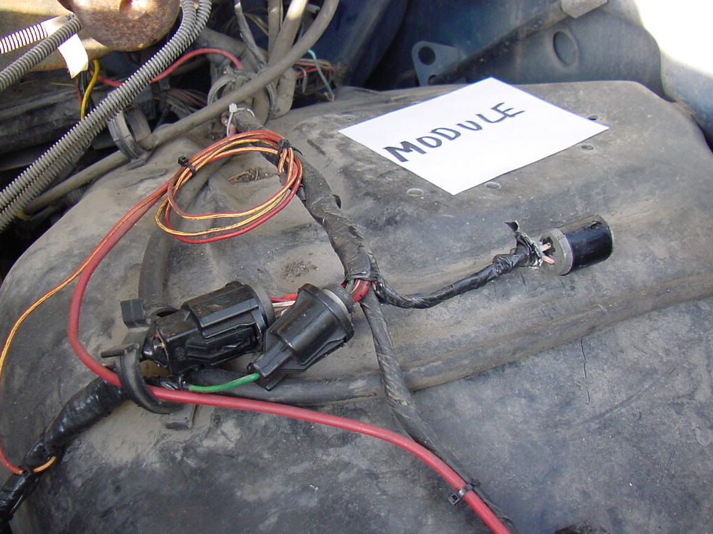
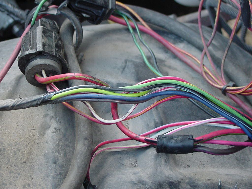
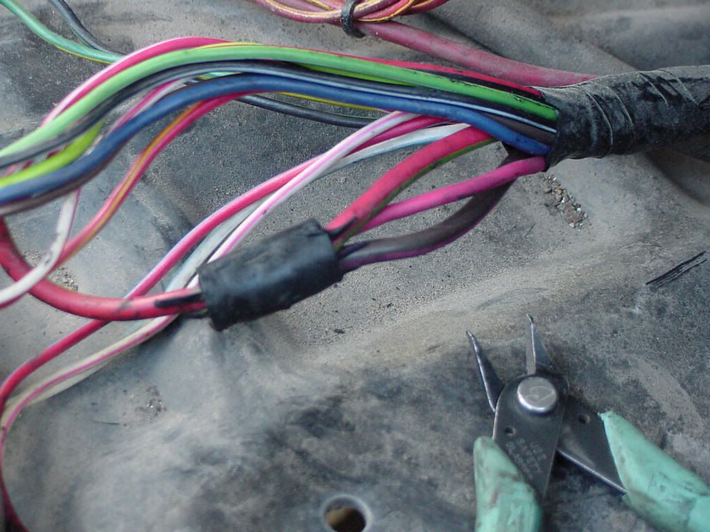
Here is a photo of the original resistor wire and and the extra bypass wire shown on top. This is a 3 in 1 out splice. The resistor wire (middle wire) is pink and has a rubbery feel to it. Also at this connection point is the original start bypass wire (bottom wire) which comes from the key switch.
Heavy-Duty External Ballast Resistor for Ignition Coils, Points and Electronic Ignition Systems ...for ballast resistor info
The ballast resistor idea would be easier but you might need to buy a starter solenoid with 2 large AND 2 small connection. I would buy the older style that has the large connections at opposite ends.
.
.