My 55 F-100 Project
#571
 06-28-2014, 11:47 PM


 )but I still can start looking into the wiring, etc.
Sorry to hear about the shoulder, I cracked a rib this winter and it sure slowed me down so I understand your plight, take care.


#573
08-26-2014, 12:25 PM
#575
08-27-2014, 08:04 AM
The floor shifter for the electronic transmission I saw was a simple cable operation, Didn't seem to be too difficult to adapt to a column shift.
#576
10-06-2014, 11:02 AM
wiring update --- no photo's
Hey guys,
Well, it has taken me all summer to configure the crown vic wiring harness to actually fit my 55.
It took me this long for 2 basic reasons, 1. I was in and out of town all summer doing fire relief and 2. It turned out to be a major pain in the *** to reconfigure the harness the way I want it.
For any of you who are considering transplanting your donor car wiring harness into your project, please pay attention to my folly.
Here is how it all started. I had the chance to strip ALL of the wiring, the instrument cluster, fuel pump / sender, lighting control module, steering column, and anything else I wanted for less than a hundred bucks at my local pull-n-save so I went for it.
I figured that it would be a no-brainer, plug and play operation and at the same time save me several grand by not having to buy new instruments, steering column, switches, fuel pumps, senders, and of course a new wiring harness.
Well, I instantly found out that the cv harness was not only WAY too long for the pickup but it was configured totally different from anything I had ever seen before. The wiring harness actually went all the way around the engine compartment and came back into the car on the passenger side and connected to the under dash harness again. (plugged in from both sides).
So, not only did I need to remove all the un-used / un-wanted circuits like air bags, traction control, variable power steering, and a host of others, but I now had to back feed all the remaining circuits that wrapped around to the right side and bring them back through the main firewall plug on the left hand side.
This is where the ford wiring manual became my bible.
Sometime in August I finished this phase and ended up with a chassis harness that was shortened about 4 feet and neatly wrapped around the engine bay from left to right and terminated at the battery junction box at the right hand side of the radiator.
Now I had to make the under dash harness fit and match my re-wired main chassis harness.
Again, I was faced with the hassle of pulling out all of the un-wanted circuits, cutting it down to fit in the space available, then re-routing all of the circuits that used to come back in from the left side to connect at the main firewall connector.
I finally test fit the modified under dash harness last night and am happy with the way it is coming out but it has been a long frustrating road to get to this point.
Just to give you some perspective on the amount of work required to make this harness fit, as of last night, I have used approximately 200 (18-22 ga) splices, 75 (14-18 ga) splices, and 20 (10-14 ga) splices.
LOL,,,,Now all I have to do is install the wiring for my add-on devices, test every circuit, wrap the finished harness and move on to the next item on my list.
In closing,,,, think long and hard before you jump into something like this, it's not terribly hard but it is time consuming and frustrating.
Gary
#577
10-06-2014, 11:25 AM
Glad to hear you're on the down hill side of the wiring. I gave up and sent my stuff to a guy to lean it out for me. $250. Seemed like a deal. Haven't installed it yet but he even sent VERY detailed instructions.
If anyone's interested:
Chuck's Roadster Electronics
12438 Hillcrest Drive
Nevada City, CA 95959
530-447-7829
Great guy to work with and the harnesses 7 in total look Factory!
If anyone's interested:
Chuck's Roadster Electronics
12438 Hillcrest Drive
Nevada City, CA 95959
530-447-7829
Great guy to work with and the harnesses 7 in total look Factory!
#578
10-07-2014, 03:09 PM
Glad to hear you're on the down hill side of the wiring. I gave up and sent my stuff to a guy to lean it out for me. $250. Seemed like a deal. Haven't installed it yet but he even sent VERY detailed instructions.
If anyone's interested:
Chuck's Roadster Electronics
12438 Hillcrest Drive
Nevada City, CA 95959
530-447-7829
Great guy to work with and the harnesses 7 in total look Factory!
If anyone's interested:
Chuck's Roadster Electronics
12438 Hillcrest Drive
Nevada City, CA 95959
530-447-7829
Great guy to work with and the harnesses 7 in total look Factory!
Thats really not a bad price considering all the head scratching involved. Did he just do the EFI harness or the chassis harness too?
#580
10-30-2014, 12:05 AM

Awesome project. Took me forever to read everything (well, scan through it is a better way to put it). I recently picked up a 04 vic for a donor. I was looking at where you moved the front ifs forwar an inch. I was curious where this measurement was taken from or based on? Did you have a reference point to work from?
#581
10-30-2014, 08:57 AM
Looks as though most folks are using the straight axle's frame mounted rubber bumper as the Iffy's center point and then moving the CV crossmember forward using the pin in the crossmember as center for the CV crossmember.
I'm planning on adding a 2003 CV crossmember to my 56 Panel this winter!
I'm planning on adding a 2003 CV crossmember to my 56 Panel this winter!
#582
11-03-2014, 05:18 PM
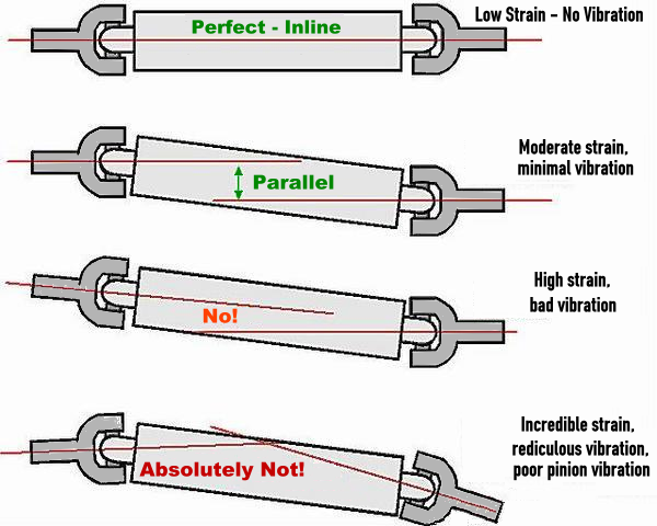
Anothet question. I was lookong at pinion angles and there are many thoughts on the subject. Just curious, when you fabbed the trans mount was there any angle to the tail shaft or were you to level it out?
Trying to figurr pinion angle and many are saying 3 deg upward but others are saying parallel with the trans tail shaft. Any thoughts.
Trying to figurr pinion angle and many are saying 3 deg upward but others are saying parallel with the trans tail shaft. Any thoughts.
#583
11-03-2014, 08:00 PM

Anothet question. I was lookong at pinion angles and there are many thoughts on the subject. Just curious, when you fabbed the trans mount was there any angle to the tail shaft or were you to level it out?
Trying to figurr pinion angle and many are saying 3 deg upward but others are saying parallel with the trans tail shaft. Any thoughts.
Trying to figurr pinion angle and many are saying 3 deg upward but others are saying parallel with the trans tail shaft. Any thoughts.
Here is a simple graphic:
#585
11-05-2014, 05:10 PM

