1970 F250 4x4 Cummins Conversion Build Thread - Lots of Pics!
#151
 03-31-2013, 09:43 PM

Join Date: Oct 2011
Location: Willard
Posts: 207
Likes: 0
Received 0 Likes
on
0 Posts
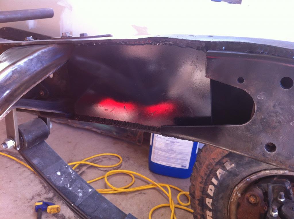
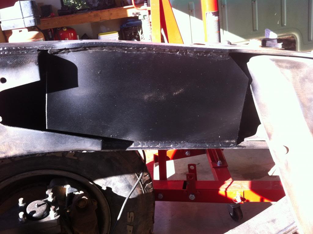
Finally back to work. Got the passenger side steel fitted to box the frame and match my work on the other side where the power steering box will mount.
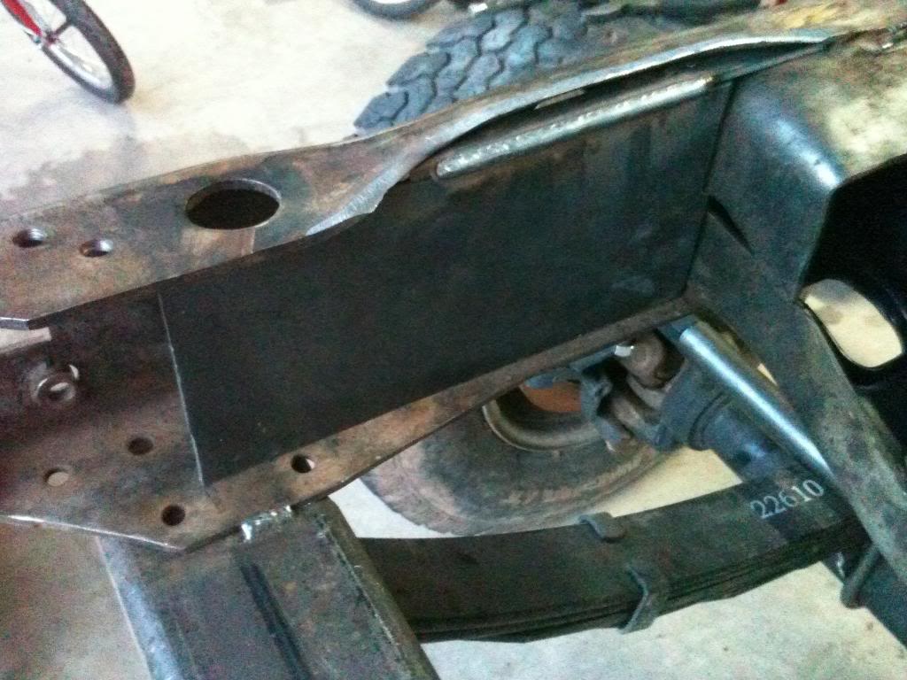
Also worked with the front crossmember to get it welded in place. I have the steel for the motor mounts, so it shouldn't be long before I tackle those bad boys.
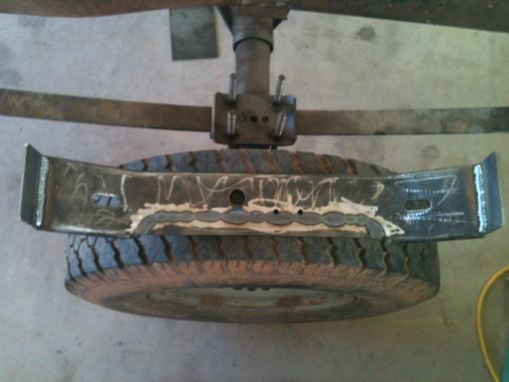
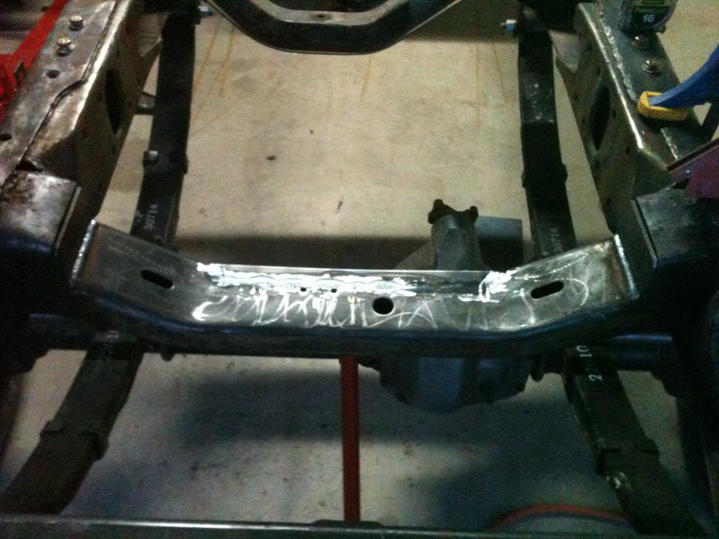
Also worked with the front crossmember to get it welded in place. I have the steel for the motor mounts, so it shouldn't be long before I tackle those bad boys.
#152
05-03-2013, 03:28 AM
Senior User
Join Date: Oct 2010
Location: Oshkosh, Ne
Posts: 277
Likes: 0
Received 0 Likes
on
0 Posts
seriously considering doing this to my 68 high boy. top end just crapped out on my 390. im actually pretty close to where you are. I live right in Grand Junction. there are a few things I am thinking about. and a donor truck is definatly where i should start i think. Im not looking to do any extra lift or anything else. right now i just want to get the motor in there, and get it going. I did like the way you did your crossmember in the front. cutting it down sure seems like the easiest way of doing it and if done well it should still look fairly stock. Im also not worried about the ac compressor issue as i wont be putting that in. the main thing i am wondering about is when i get everything together for it and start on it how do i tie into my drivetrain? do you have to get new drive lines made, fab crossmembers for the new trans and transfer case? also do you have to completely redo your entire instrument cluster? and how does the wiring situation work out under the hood?
I know that is alot of questions and all, sorry to interrupt your build thread, im just curious if this is even a project i should undertake. Thanks
I know that is alot of questions and all, sorry to interrupt your build thread, im just curious if this is even a project i should undertake. Thanks
#153
05-03-2013, 06:35 PM
Logistics Pro
#154
05-06-2013, 02:58 PM
Cargo Master
Join Date: Nov 2005
Location: La Ribera, Baja, Mexico
Posts: 2,694
Likes: 0
Received 42 Likes
on
24 Posts
Extremely nice conversion, and done at the 'Speed of Right'. I will keep your project in mind the next time I get impatient to finish something in a hurry. Well done amigo. I took 2 years to restore my '67, and glad that I took the time I did. I have one of those 'Rockcrawler' boxes I did not use, in case you know someone needing one.
Baja
Baja
#155
05-10-2013, 10:26 PM
Join Date: Oct 2011
Location: Willard
Posts: 207
Likes: 0
Received 0 Likes
on
0 Posts
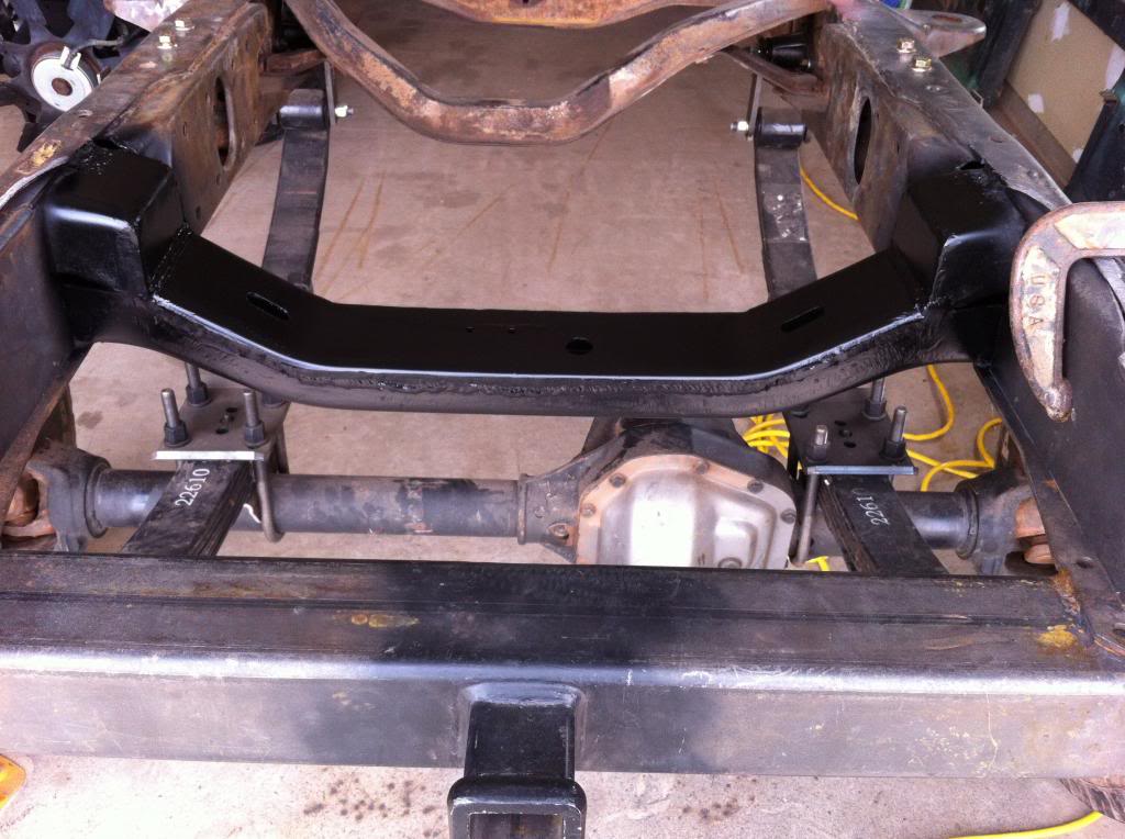
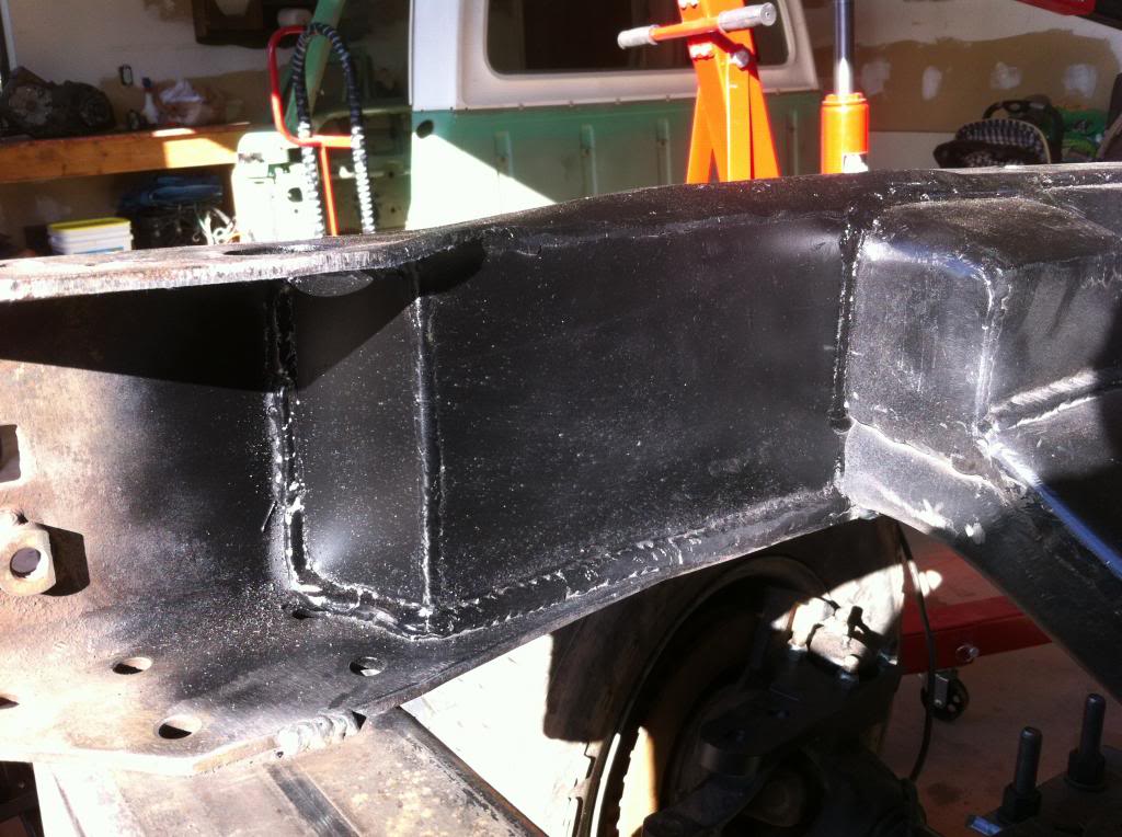
I am still chipping away at this guy in my free time. Front crossmember is done. Frame is boxed on the passenger side. I still need to get the frame boxed on the drivers side and then I will be ready to build the motor mounts. I am honestly not in a hurry because I know that the financial well has dried up for a while, so I am not racing to get to that next step.
I estimate that it is going to take about $12,000 to finish this project. I don't know where that is going to come from, so I am taking my time. If I had the funds, this thing would be done this summer for sure. Too many expensive parts to buy
In short, yes. The basic conversion would require motor mounts built, radiator / intercooler mounting fab, trans & transfercase crossmembers fabricated, and new drivelines. As far as wiring and gauges on a stock vehicle, I really don't know because I am using a custom wiring kit and aftermarket gauges. 12 valves are not that complicated, so wiring shouldn't be too difficult as long as you are comfortable playing around with a test light.
I don't know your mechanical ability, but don't think this is going to be a weekend job. It will take a good deal of dedication and resources over several months. Buying a donner truck is the way to go in my opinion. That way, you can part out the truck and make some of your money back.
You are welcome to stop by and take a look at the project if you head out this way. I actually live in Castle Valley. I buy steel in Grand Junction at Pacific Steel. They have always treated me right.

I estimate that it is going to take about $12,000 to finish this project. I don't know where that is going to come from, so I am taking my time. If I had the funds, this thing would be done this summer for sure. Too many expensive parts to buy
seriously considering doing this to my 68 high boy. top end just crapped out on my 390. im actually pretty close to where you are. I live right in Grand Junction. there are a few things I am thinking about. and a donor truck is definatly where i should start i think. Im not looking to do any extra lift or anything else. right now i just want to get the motor in there, and get it going. I did like the way you did your crossmember in the front. cutting it down sure seems like the easiest way of doing it and if done well it should still look fairly stock. Im also not worried about the ac compressor issue as i wont be putting that in. the main thing i am wondering about is when i get everything together for it and start on it how do i tie into my drivetrain? do you have to get new drive lines made, fab crossmembers for the new trans and transfer case? also do you have to completely redo your entire instrument cluster? and how does the wiring situation work out under the hood?
I don't know your mechanical ability, but don't think this is going to be a weekend job. It will take a good deal of dedication and resources over several months. Buying a donner truck is the way to go in my opinion. That way, you can part out the truck and make some of your money back.
You are welcome to stop by and take a look at the project if you head out this way. I actually live in Castle Valley. I buy steel in Grand Junction at Pacific Steel. They have always treated me right.
#156
05-10-2013, 10:31 PM
Join Date: Oct 2011
Location: Willard
Posts: 207
Likes: 0
Received 0 Likes
on
0 Posts
#157
05-11-2013, 08:27 AM
Cargo Master
Join Date: Nov 2005
Location: La Ribera, Baja, Mexico
Posts: 2,694
Likes: 0
Received 42 Likes
on
24 Posts
I found it on Ebay, when I was doing the conversion to P/S on my Highboy. I bought it, and had it shipped to San Diego. It obviously is the heaviest duty 4x4 P/S gearbox ever made. It weighs over 40 lbs, and the 4 bolt spread is at least 7". It is made to fit on the inside of the frame, and looks like some minor cross member alteration is necessary to get a wrench on one of the lower, rear bolts.
I opted for another box, which I will attempt to download some photos of later, and it fits on the outside of the frame, with the pittman arm switched 180 deg. so it sticks out towards the tire. I had clearance for the drag link, even with MT 325x75x17 tires & rims.
Unfortunately, I hauled it 1000 miles down Baja, before discovering that I was going to use the 2nd (and lighter weight) gearbox. When I get home in late May, I will post some photos.
Baja
#158
05-11-2013, 08:30 AM
Cargo Master
Join Date: Nov 2005
Location: La Ribera, Baja, Mexico
Posts: 2,694
Likes: 0
Received 42 Likes
on
24 Posts
I found it on Ebay, when I was doing the conversion to P/S on my Highboy. I bought it, and had it shipped to San Diego. It obviously is the heaviest duty 4x4 P/S gearbox ever made. It weighs over 40 lbs, and the 4 bolt spread is at least 7". It is made to fit on the inside of the frame, and looks like some minor cross member alteration is necessary to get a wrench on one of the lower, rear bolts.
I opted for another box, which I will attempt to download some photos of later, and it fits on the outside of the frame, with the pittman arm switched 180 deg. so it sticks out towards the tire. I had clearance for the drag link, even with MT 325x75x17 tires & rims.
Unfortunately, I hauled it 1000 miles down Baja, before discovering that I was going to use the 2nd (and lighter weight) gearbox. When I get home in late May, I will post some photos.
Baja
I opted for another box, which I will attempt to download some photos of later, and it fits on the outside of the frame, with the pittman arm switched 180 deg. so it sticks out towards the tire. I had clearance for the drag link, even with MT 325x75x17 tires & rims.
Unfortunately, I hauled it 1000 miles down Baja, before discovering that I was going to use the 2nd (and lighter weight) gearbox. When I get home in late May, I will post some photos.
Baja
#160
05-11-2013, 09:16 AM
Join Date: Oct 2011
Location: Willard
Posts: 207
Likes: 0
Received 0 Likes
on
0 Posts
OK amigos,
I just went on Ebay, and typed in "79 Ford 4x4 P/S steering box" and one came up... The one I have looks just like this one off a F350, with the large spread 4 bolt pattern, and the heavy duty box. Mine looks to be in extremely good shape.. with no rust at all..
Baja
I just went on Ebay, and typed in "79 Ford 4x4 P/S steering box" and one came up... The one I have looks just like this one off a F350, with the large spread 4 bolt pattern, and the heavy duty box. Mine looks to be in extremely good shape.. with no rust at all..
Baja

#161
05-12-2013, 08:25 AM
Cargo Master
Join Date: Nov 2005
Location: La Ribera, Baja, Mexico
Posts: 2,694
Likes: 0
Received 42 Likes
on
24 Posts
Yep, its the same one... I found (on Ebay again), a reman, which mounts to the outisde of the frame, only requiring a spacer plate on the inside, and rotation of the pitman arm 180 deg. They are indexed anyway, so it was easy. I will try to download some photos, but I am not the photograper you are, by any measure.
Baja..
"Proceed at the Speed of Right, and you will never go wrong"
Baja..
"Proceed at the Speed of Right, and you will never go wrong"
#162
06-19-2013, 09:12 AM
Join Date: Oct 2011
Location: Willard
Posts: 207
Likes: 0
Received 0 Likes
on
0 Posts
Finally, a long overdue update. Work has been keeping me busy, but with the likelihood of moving looming in the near future - the pressure is on to get the major pieces in place!
Finished boxing the frame.
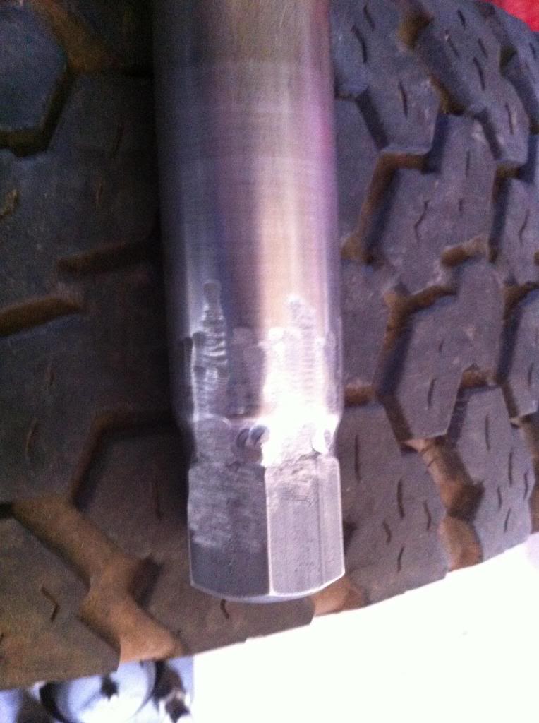
Now time to finish up the drag link so I can maneuver this beast around. I used a lathe to 45 the end of the drag link tube to make a nice welding surface.
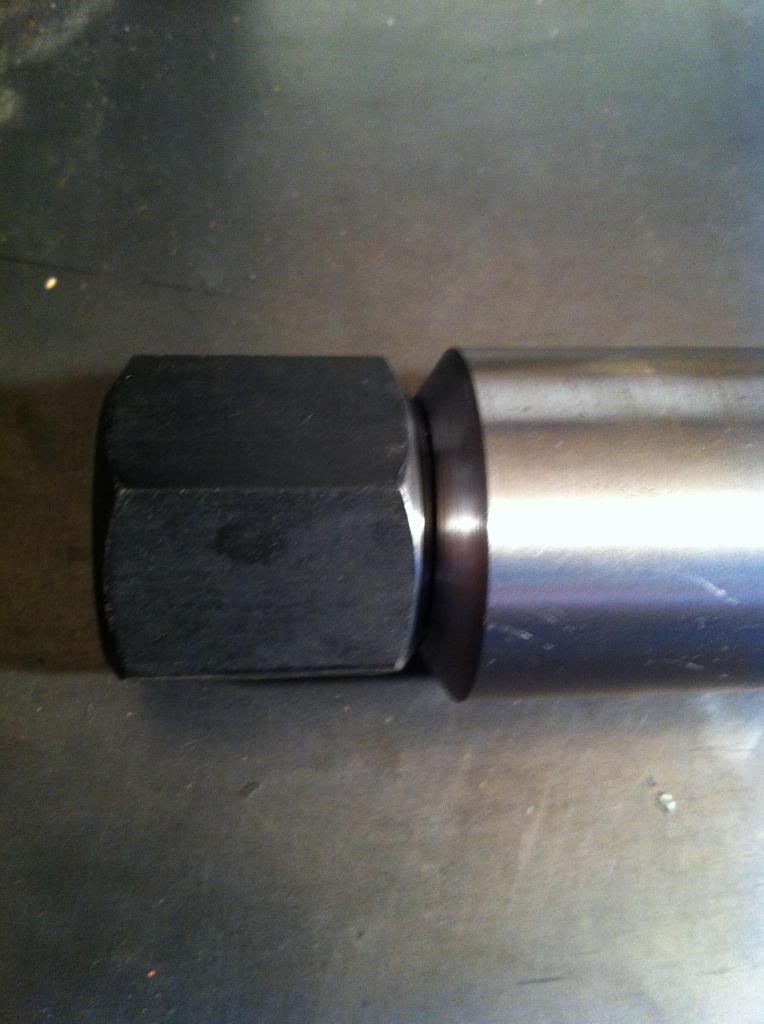
My friend who is shop owner and a 4x4 specialist insisted that all steering components be tig welded to keep the heat down and increase strength. He said that steering is one place where you don't want to go cheap. I had him tig weld the drag link for me and then I smoothed out the edges with a grinder and sandpaper on the lathe.
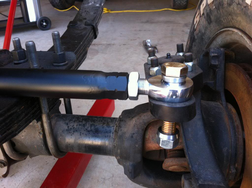
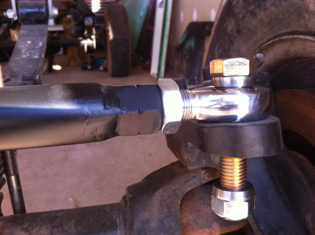
Painted and installed.
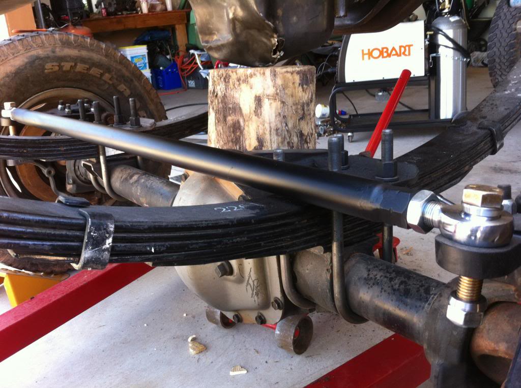
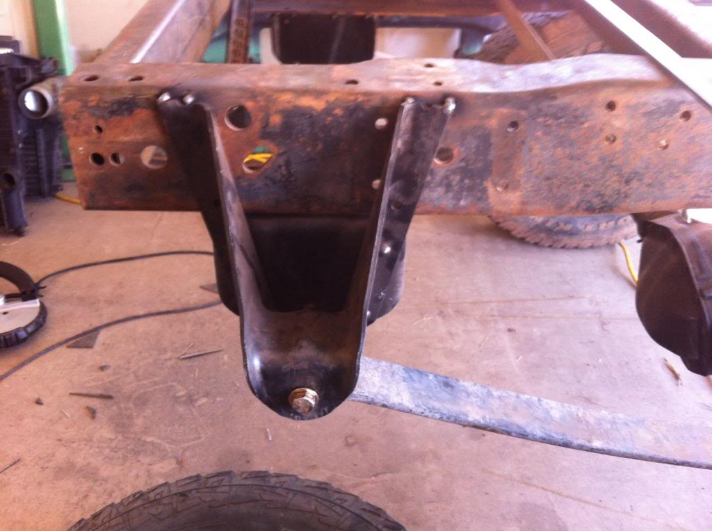
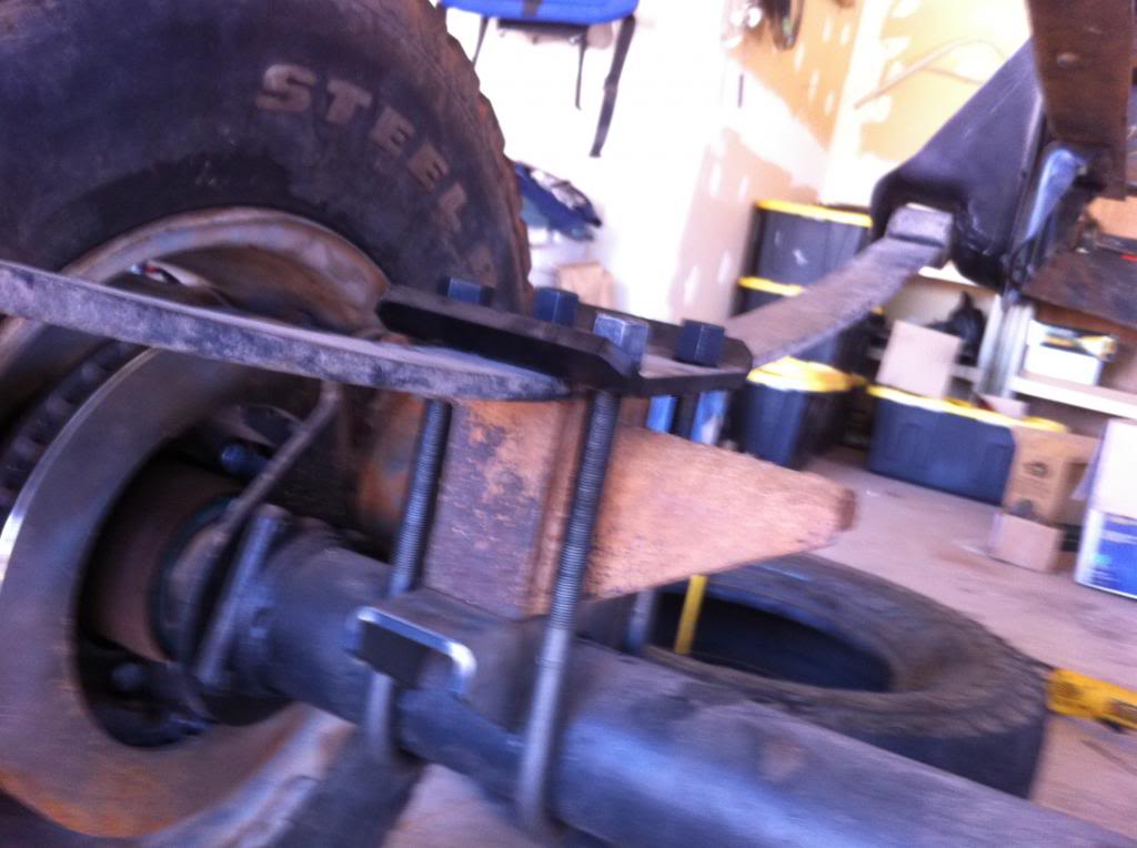
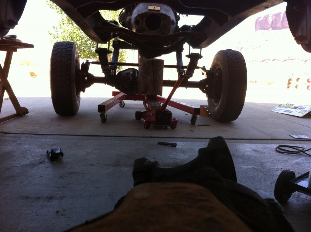
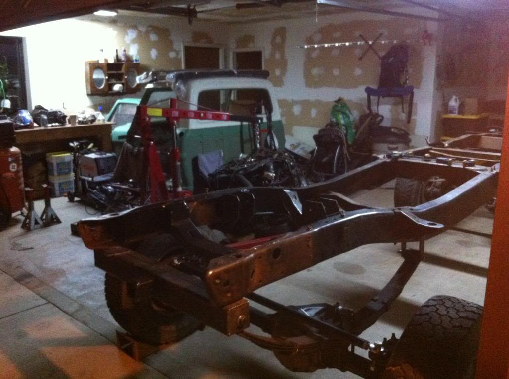
I had to get the rear ride hight as close as possible to get the correct pinion angle reference to mount the engine at the right angle also. I tacked the rear hangers in place and used the stock Ford lift blocks to raise things up to the proper height. Surprisingly, ride hight came out just about perfect using this set up. This will be good enough to get the engine mounted and transport the vehicle when I move.
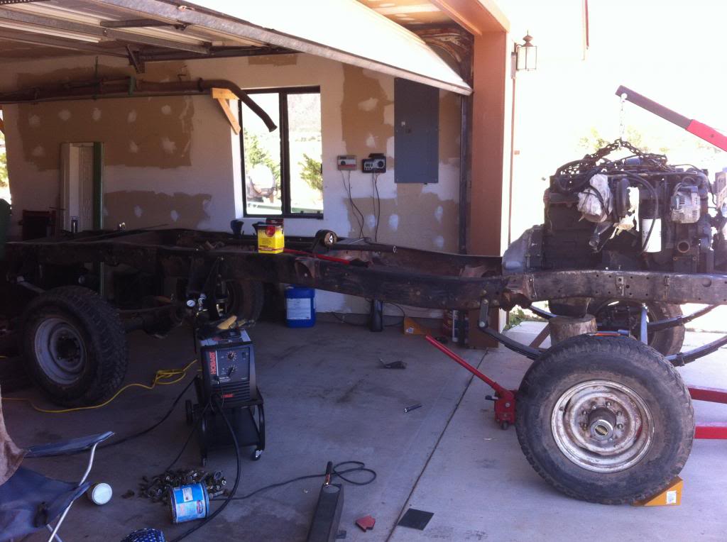
Finally, the motor is going in! Engine has been set in the correct location to build the mounts.
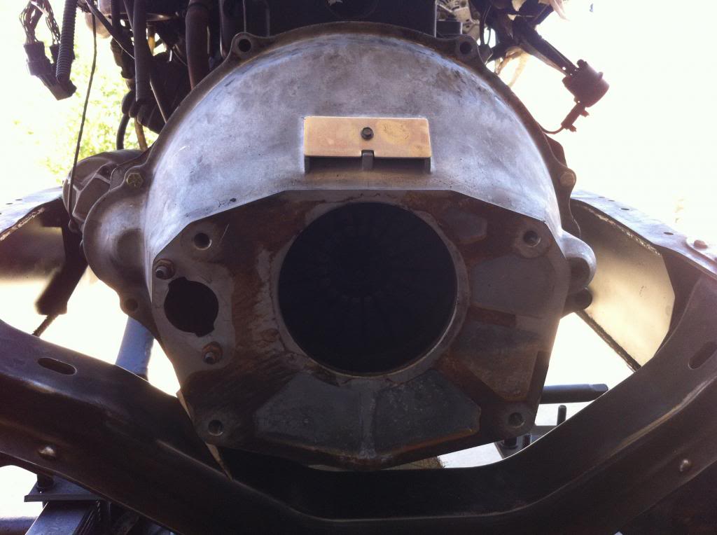
The ideal is to get the engine as low in the frame as possible to keep things from being tipsy and keep a low center of gravity. You also want the engine angle to match the rear axle pinion angle as closely as possible within reason. You don't want the engine output shaft to be directly in line with the pinion on the rear axle, but rather 3 to 4 degrees off. This allows the u-joint to make a full rotation rather than just wearing in one spot. If you don't change the cross member under the bell housing and you are using a 14 bolt rear axle, it won't be possible to center the output shaft and rear axle and the correct angle will be self evident. Notice that the engine is sloped front to rear in the frame for better drive shaft angle.
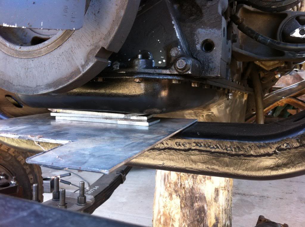
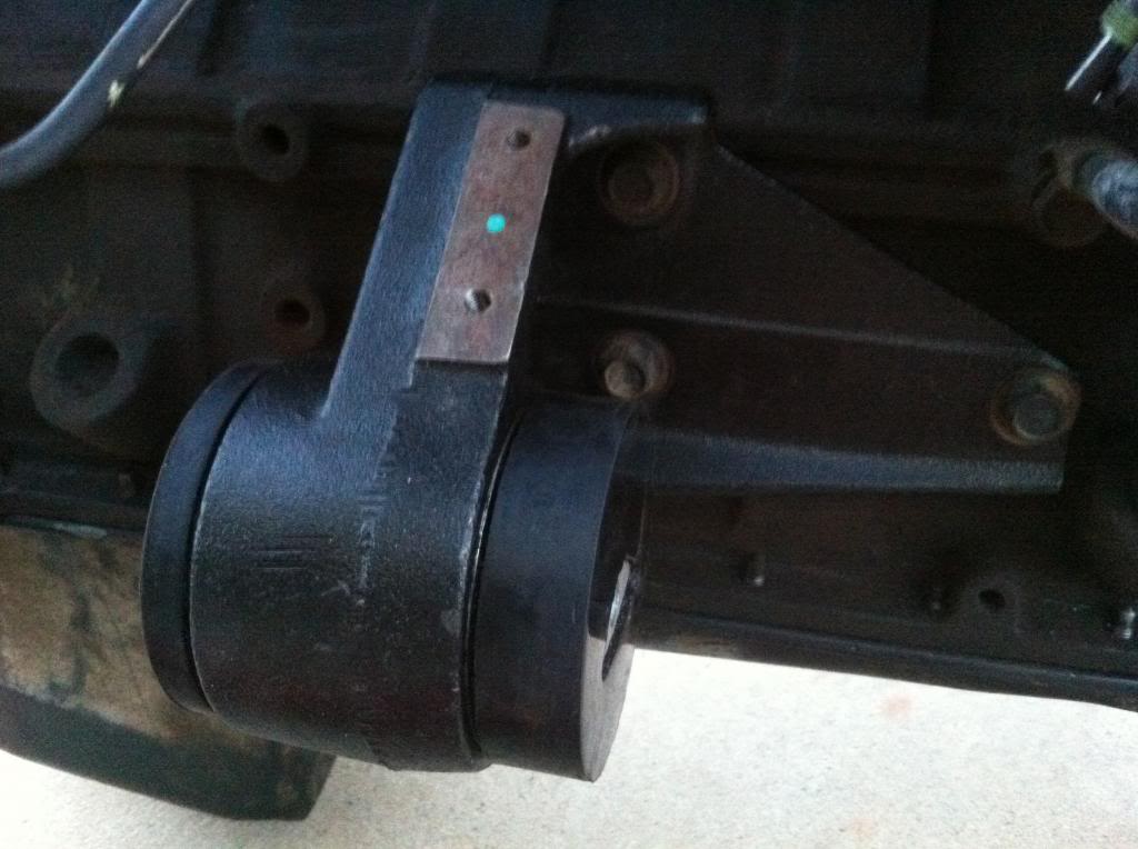
Here are the mounts and how I made them. I am using the stock dodge mounts off the engine and will build around them.
I cut out matching pieces of 3/16" steel for each side and shaped them accordingly.
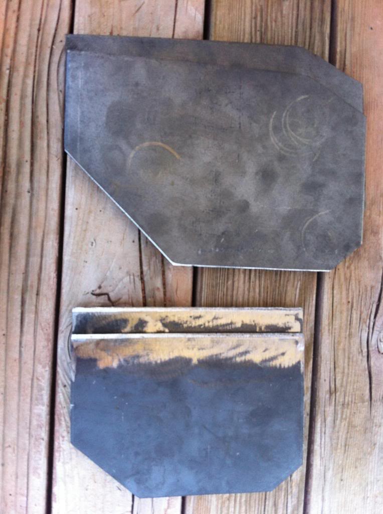
I went ahead and drilled in the correct location based on how my engine was sitting in the frame. I also beveled the edges on both sides of my hole.
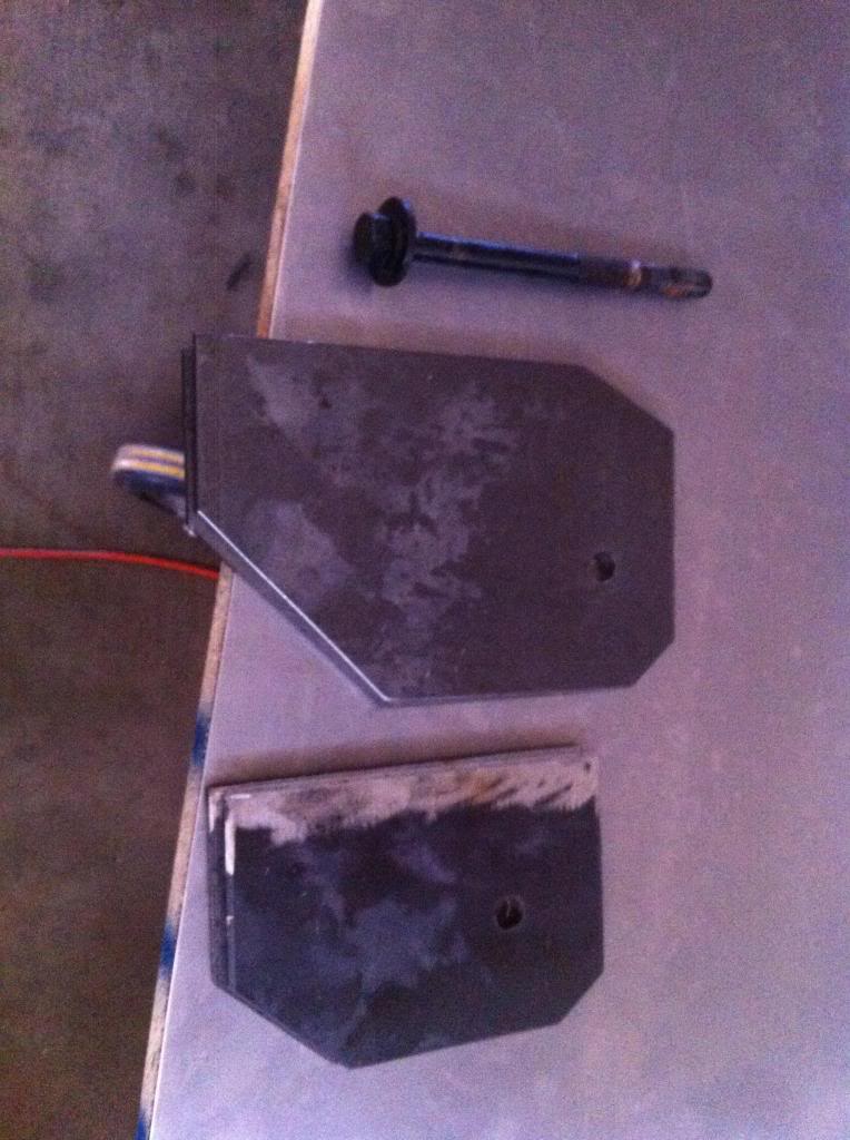
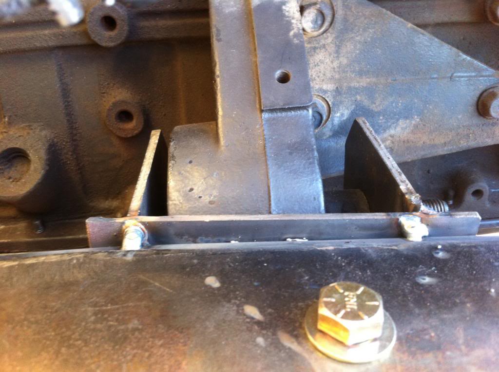
Here they are getting tacked in place. Notice that the ears on the mount are slightly higher and lower respectively to match the angle of the engine. There was a 1/4" slope over the distance of the mount (4").
Motors back out to finish welding, bolting, and gusseting these in place.
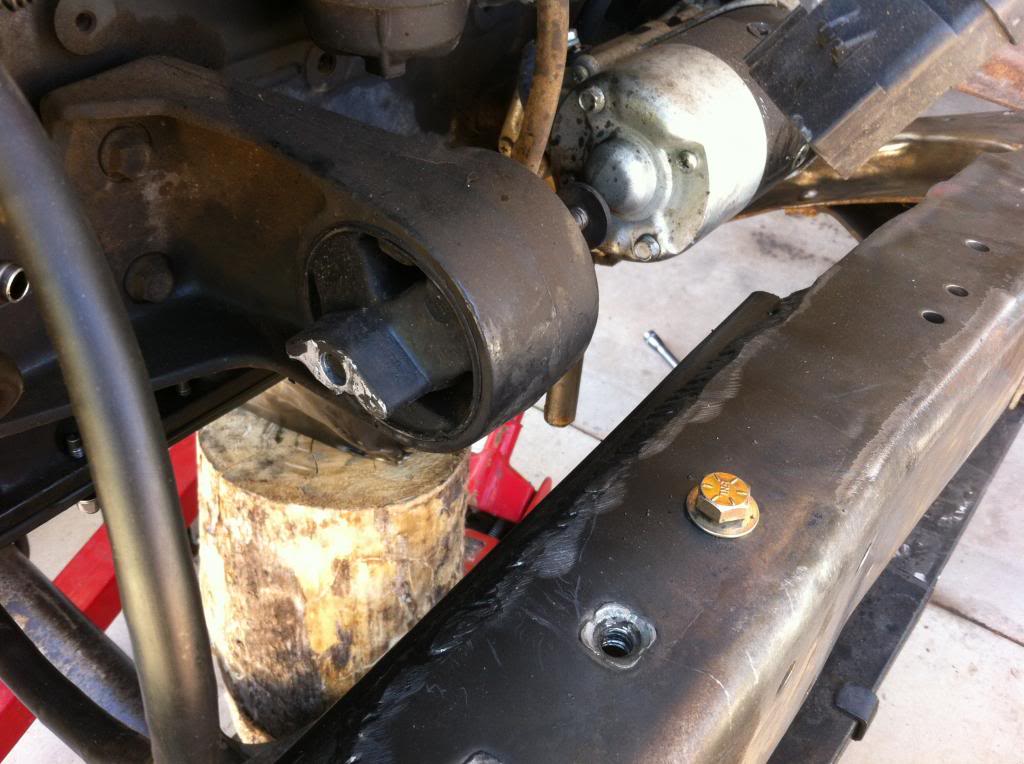
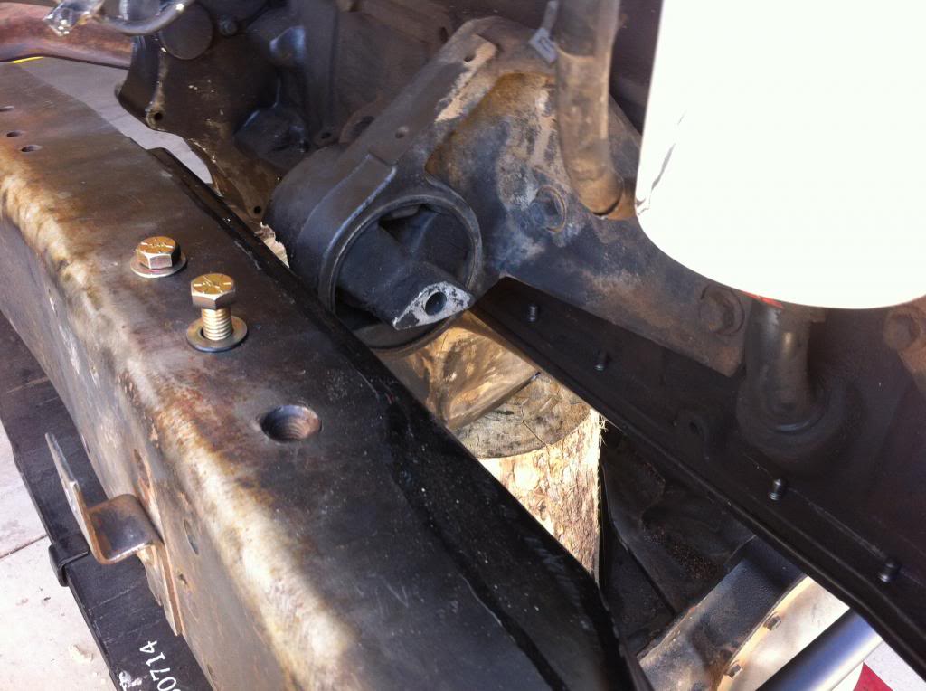
Installed the new dodge motor mount to replace my worn out one and installed polyurethane inserts. Interestingly, the polyurethane inserts fit perfectly on the side with the new mount, but required heavy modification to fit the other side.
It's late, everything is back in the shop and I will continue tomorrow.
Now if my corn would hurry up and start growing!

Finished boxing the frame.


Now time to finish up the drag link so I can maneuver this beast around. I used a lathe to 45 the end of the drag link tube to make a nice welding surface.

My friend who is shop owner and a 4x4 specialist insisted that all steering components be tig welded to keep the heat down and increase strength. He said that steering is one place where you don't want to go cheap. I had him tig weld the drag link for me and then I smoothed out the edges with a grinder and sandpaper on the lathe.

Painted and installed.


I had to get the rear ride hight as close as possible to get the correct pinion angle reference to mount the engine at the right angle also. I tacked the rear hangers in place and used the stock Ford lift blocks to raise things up to the proper height. Surprisingly, ride hight came out just about perfect using this set up. This will be good enough to get the engine mounted and transport the vehicle when I move.


Finally, the motor is going in! Engine has been set in the correct location to build the mounts.


The ideal is to get the engine as low in the frame as possible to keep things from being tipsy and keep a low center of gravity. You also want the engine angle to match the rear axle pinion angle as closely as possible within reason. You don't want the engine output shaft to be directly in line with the pinion on the rear axle, but rather 3 to 4 degrees off. This allows the u-joint to make a full rotation rather than just wearing in one spot. If you don't change the cross member under the bell housing and you are using a 14 bolt rear axle, it won't be possible to center the output shaft and rear axle and the correct angle will be self evident. Notice that the engine is sloped front to rear in the frame for better drive shaft angle.

Here are the mounts and how I made them. I am using the stock dodge mounts off the engine and will build around them.
I cut out matching pieces of 3/16" steel for each side and shaped them accordingly.

I went ahead and drilled in the correct location based on how my engine was sitting in the frame. I also beveled the edges on both sides of my hole.

Here they are getting tacked in place. Notice that the ears on the mount are slightly higher and lower respectively to match the angle of the engine. There was a 1/4" slope over the distance of the mount (4").


Motors back out to finish welding, bolting, and gusseting these in place.


Installed the new dodge motor mount to replace my worn out one and installed polyurethane inserts. Interestingly, the polyurethane inserts fit perfectly on the side with the new mount, but required heavy modification to fit the other side.

It's late, everything is back in the shop and I will continue tomorrow.

Now if my corn would hurry up and start growing!

#163
06-19-2013, 11:06 PM
Join Date: Oct 2011
Location: Willard
Posts: 207
Likes: 0
Received 0 Likes
on
0 Posts
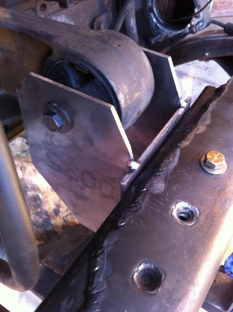
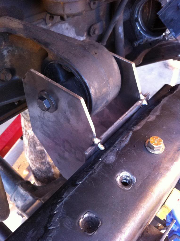
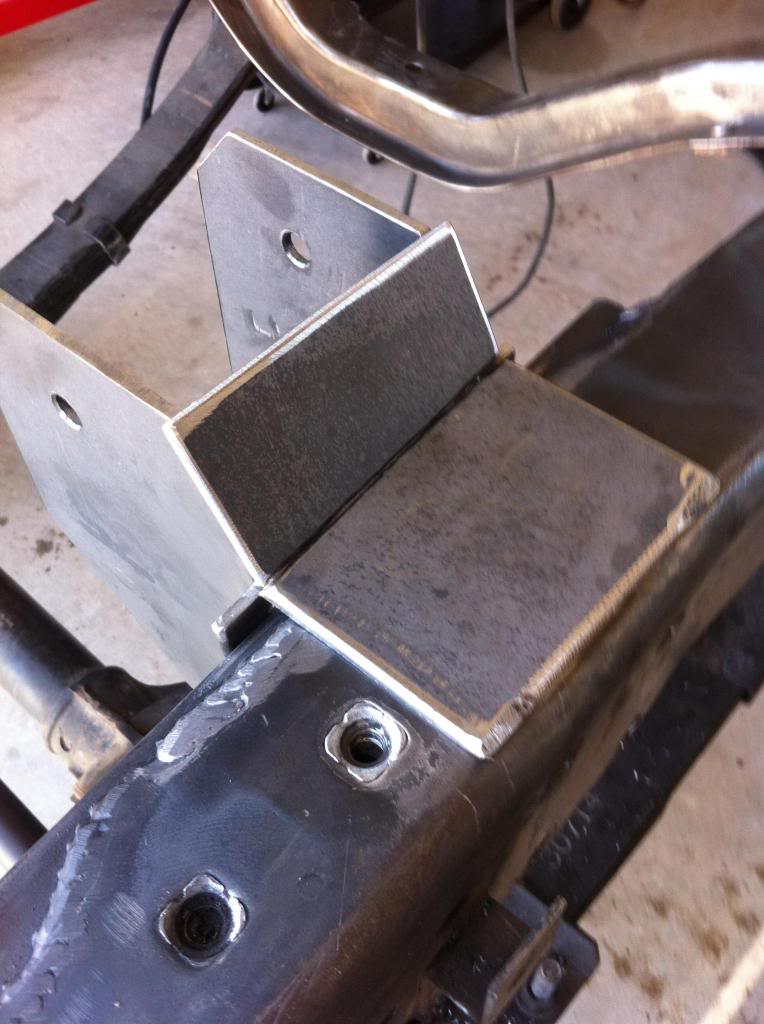
Back to work. Started out by using the factory holes as a guide to drill through the mounts. I will be using bolts, but I also will be welding the mounts to the frame a little bit. I don't want to lay a fat bead all around the mounts because all that heat may weaken the frame in that area. So, I will go with bolts and a little bit of welding here and there where it counts.
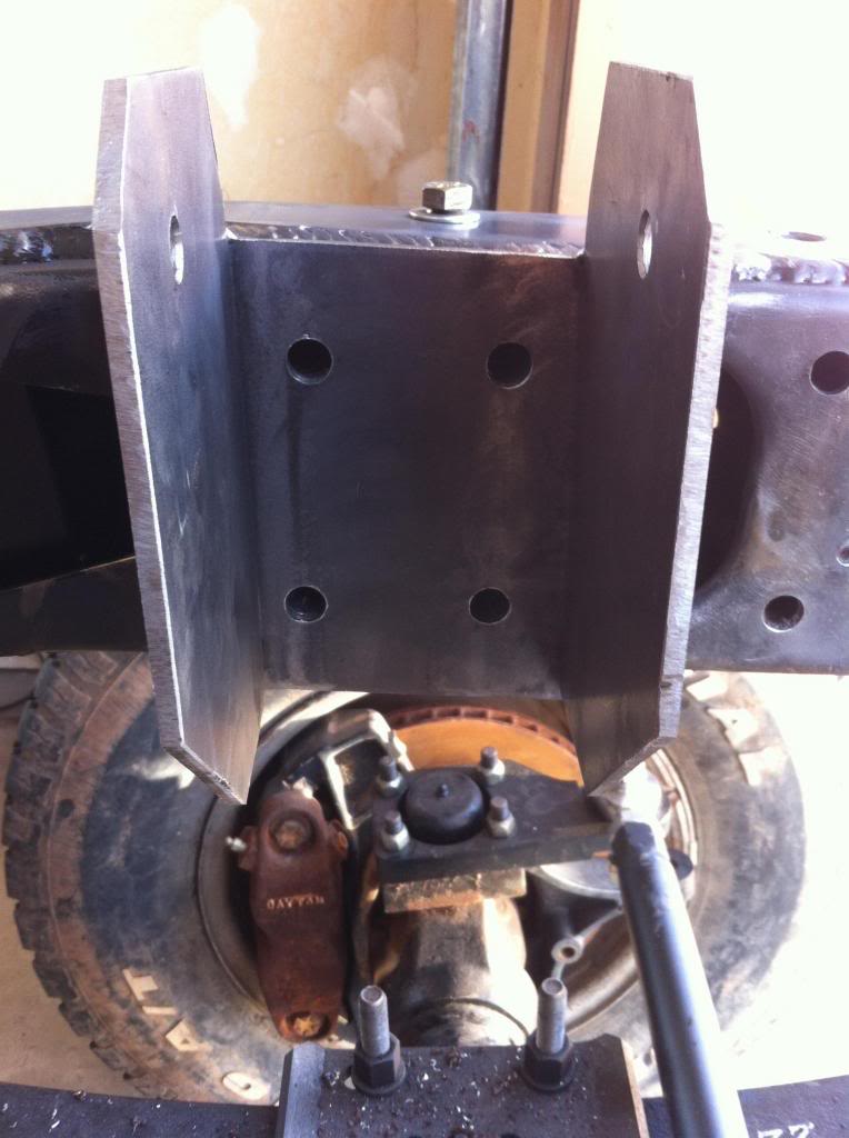
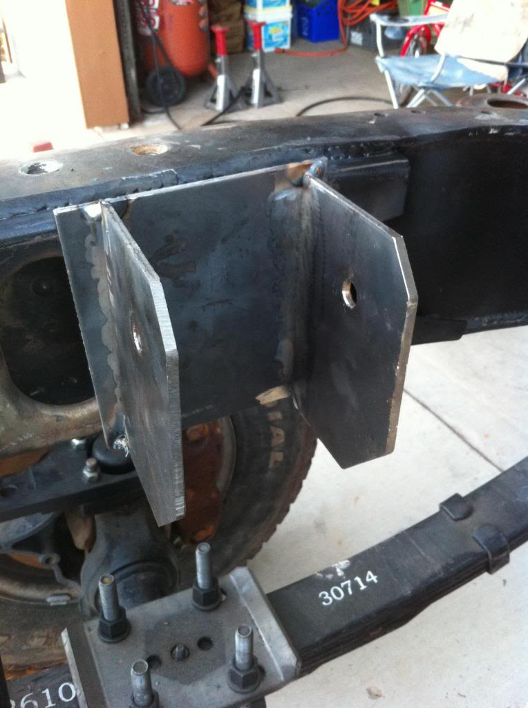
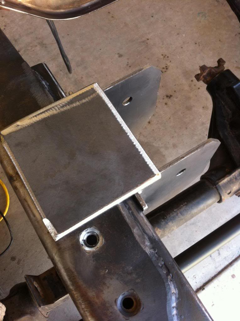
I cut out the plates that will connect to the mounts and bolt to the frame.
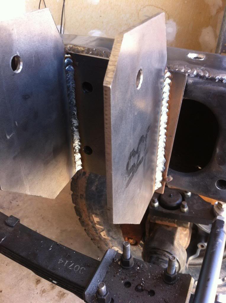
Welded up the mount ears solid.
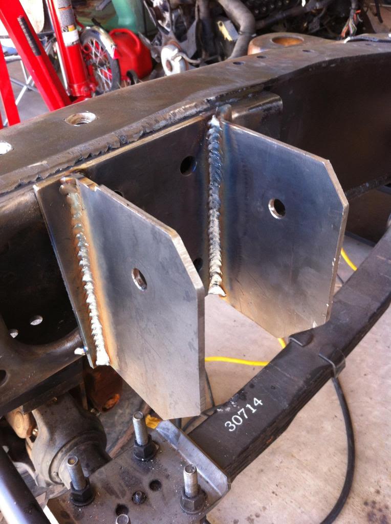
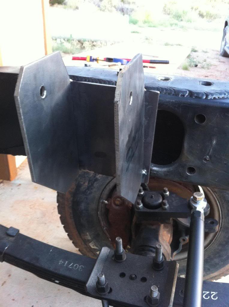
Plates are drilled and ready to weld.
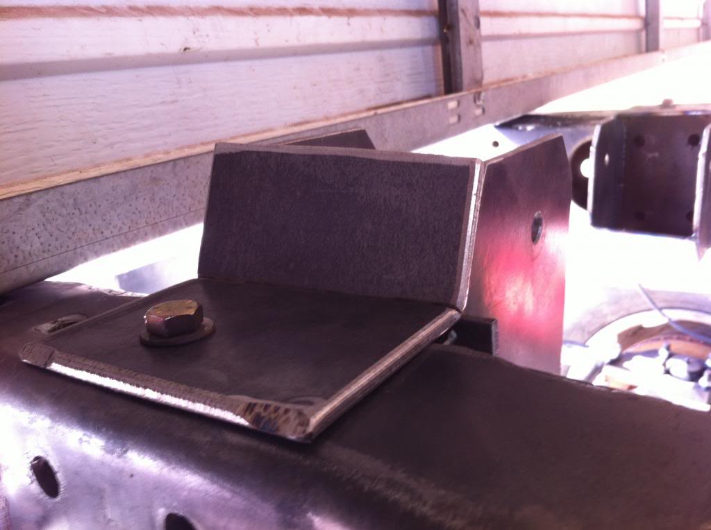
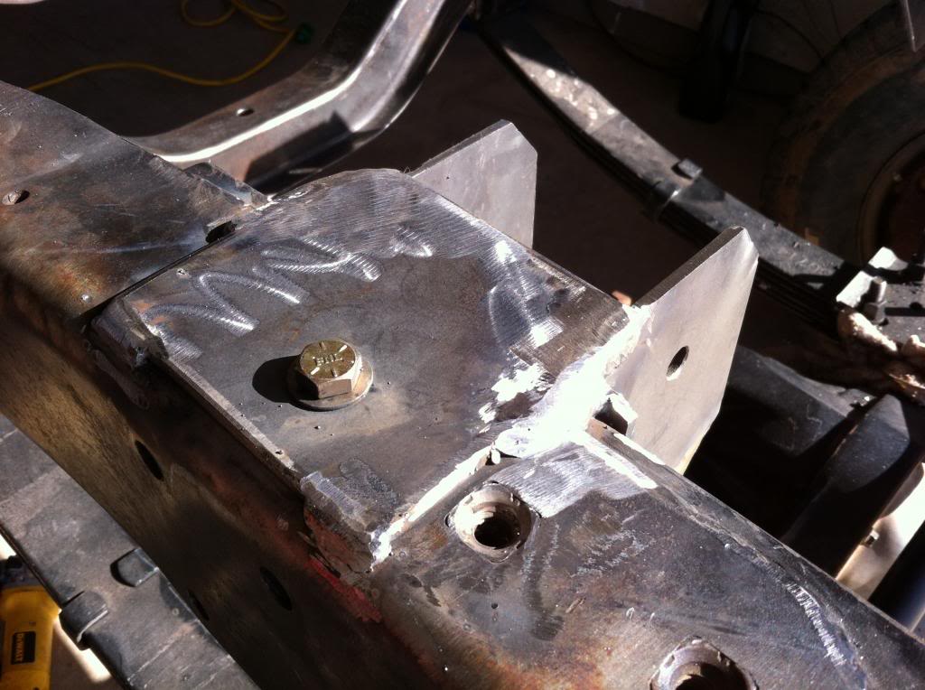
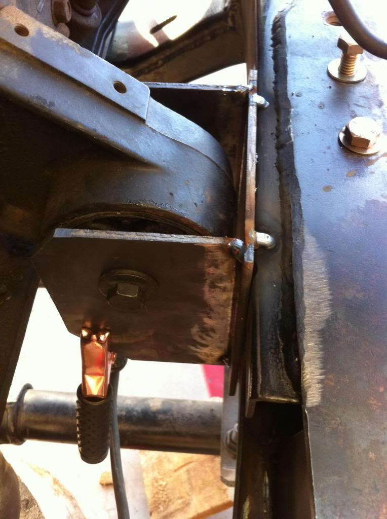
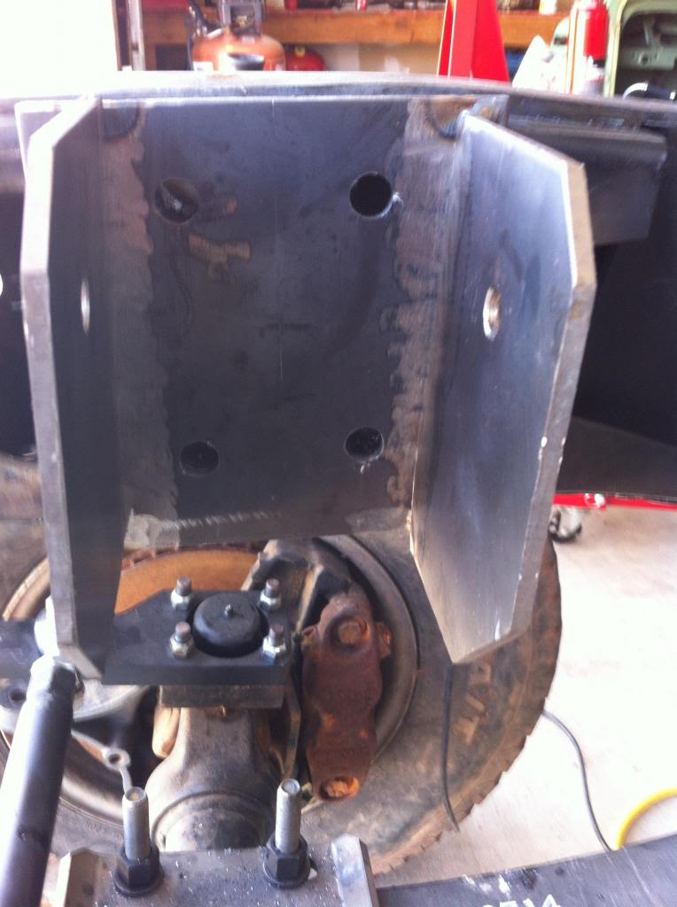
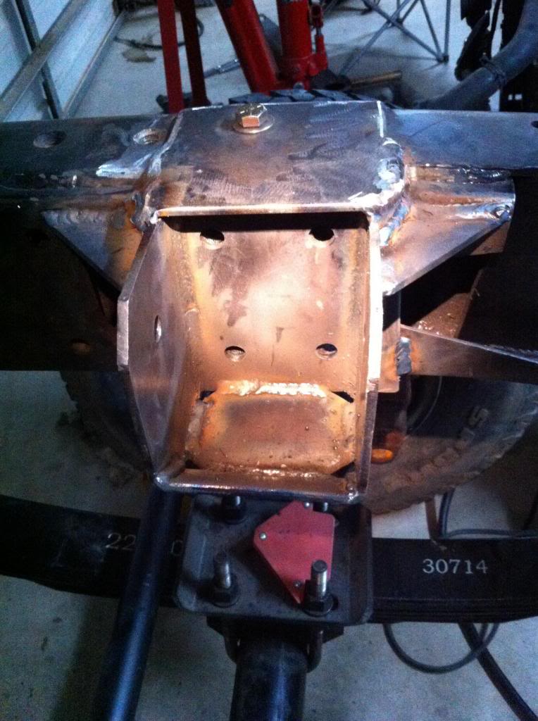
Passenger side needs to be cleaned up, but is basically done. I added the gussets on the top that connect to the frame to keep the mount ears from wandering. Also, i cut the corners out of the plate on the bottom of the mount so water and debris can escape.


I cut out the plates that will connect to the mounts and bolt to the frame.


Welded up the mount ears solid.


Plates are drilled and ready to weld.


Passenger side needs to be cleaned up, but is basically done. I added the gussets on the top that connect to the frame to keep the mount ears from wandering. Also, i cut the corners out of the plate on the bottom of the mount so water and debris can escape.

#164
06-21-2013, 10:38 AM
Join Date: Oct 2011
Location: Willard
Posts: 207
Likes: 0
Received 0 Likes
on
0 Posts


#165
06-21-2013, 04:14 PM
Join Date: Oct 2011
Location: Willard
Posts: 207
Likes: 0
Received 0 Likes
on
0 Posts


