6v to 12v Ignition Confusion
#1
 02-24-2012, 01:09 PM


Join Date: Feb 2012
Location: Pflugerville, Texas
Posts: 104
Likes: 0
Received 0 Likes
on
0 Posts
6v to 12v Ignition Confusion
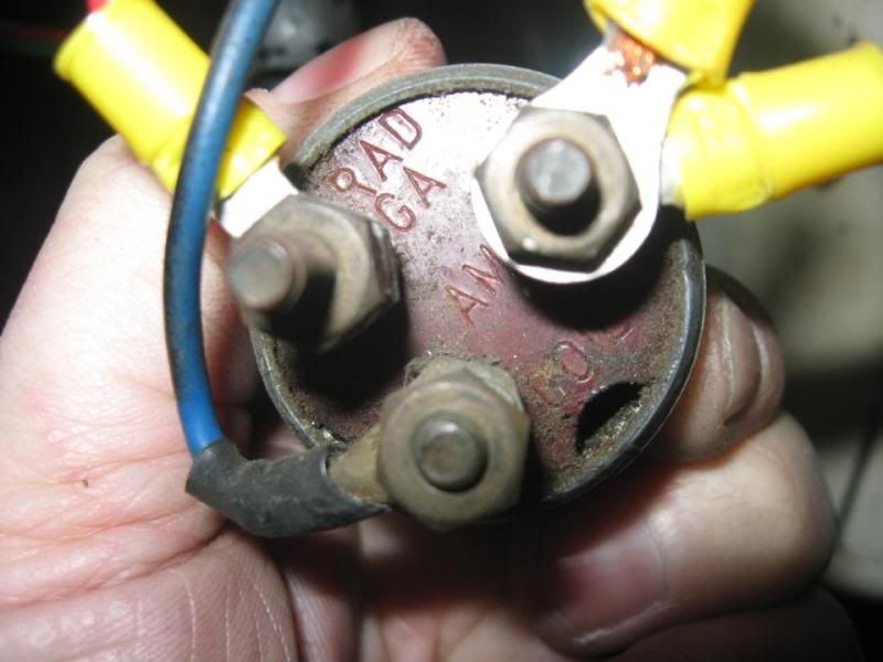
I'm starting my 12v conversion and am hooking up the ignition system with a new ignition switch and ran into a block.
- On the old ignition switch there is a coil terminal with a direct wire to the 6v coil. Am I supposed to move that cable to the terminal marked "I" in the new starter relay or move it to the terminal marked "IGN" on the new ignition switch?
- Where do I move the wires on the terminal marked "RAD GA" old ignition switch to the new switch. I assume "RAD GA" stands for radio and gauges? Am I supposed to move it to the terminal marked "ACC" (accessory I guess)
- What does the terminal marked "AM" go to? Is it ammeter and should it go to the terminal marked "BAT" on the new ignition switch?
- What is the terminal post in the center of the new ignition switch for?
I apologize for all of the questions, but I left my shop manual at work.
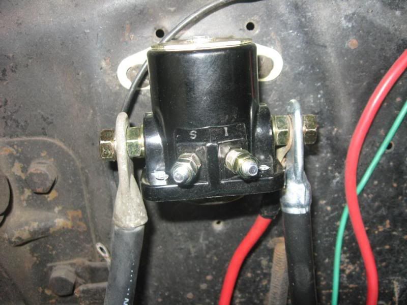
Here are pics of the old and new ignition switches and new starter relay:
Old Ignition
New Ignition

New Starter Relay
- On the old ignition switch there is a coil terminal with a direct wire to the 6v coil. Am I supposed to move that cable to the terminal marked "I" in the new starter relay or move it to the terminal marked "IGN" on the new ignition switch?
- Where do I move the wires on the terminal marked "RAD GA" old ignition switch to the new switch. I assume "RAD GA" stands for radio and gauges? Am I supposed to move it to the terminal marked "ACC" (accessory I guess)
- What does the terminal marked "AM" go to? Is it ammeter and should it go to the terminal marked "BAT" on the new ignition switch?
- What is the terminal post in the center of the new ignition switch for?
I apologize for all of the questions, but I left my shop manual at work.
Here are pics of the old and new ignition switches and new starter relay:
Old Ignition
New Ignition
New Starter Relay
#2
02-24-2012, 02:01 PM
The center post on the new switch is for the 'start' function. On the old 6v setup it is done by the seperate starter button. You can set your new switch up either way.
RAD GA would be the equivilent to the ACC on the new switch.
AM goes to the BAT terminal on the new switch.
COIL goes to the IGN on the new switch.
Just out of curiosity.... why are you changing the switch? You do know that 6V switches work on a 12v system, right? However 12v switches WILL NOT work on a 6v system. You will also need voltage reducers for your gauges, heater, radio, and change out all your bulbs to 12V bulbs. If using the stock starter, it will have to be converted to 12 volt and the horn and relay will need a reduction in voltage aswell. (actually the relay should be fine, but either way the horn will need to be 6V. Make sure that your coil is a 12v coil and if you have points that there is an ign resistor between the coil and the Ignition switch. Before you add the resistor, check your voltage at the end of the wire that goes tothe coil and make sure you are gettin 12v. This just doubble checks to see if you have a resistor wire or not. (i'm not sure if you are using existing wiring or something else- coverin my bases) If it is less that 12v (in the realm of 7-9 volts) then you will not need an in-line resistor.
For wiring up your starter button using the new switch, do not use the center terminal.
If you want the button 'hot' all the time (will crank with key off) -Connect a wire from the button to the BAT terminal (probaby is one of those two wires on your AM post now) to one side of the starter switch. Then from the switch to the 'S' terminal on the Starter relay. Should be the way it is originally.
If you want it to crank only when the key is 'on' -Connect a wire to the ACC terminal (or you could use the IGN terminal but this could cause issues...) then to one side of the starter switch and from the starter switch to the 'S' terminal on the solenoid.
Last edited by Dano78; 02-24-2012 at 02:25 PM. Reason: Addin more stuff...
#3
02-24-2012, 02:13 PM
Join Date: Feb 2012
Location: Pflugerville, Texas
Posts: 104
Likes: 0
Received 0 Likes
on
0 Posts
#4
02-24-2012, 02:31 PM
If you do not want to use the starter button, then yes, you'll need the more modern 12v switch that has the extra 'start' function.
To wire that up, you'll just run a wire from the 'start' terminal on the switch straight to the "S" terminal on the soleniod.
Make sure you 'omit' the original wiring to and from the starter button if it is still there as it will be hot if hooking everything back up 'as it was'.
To wire that up, you'll just run a wire from the 'start' terminal on the switch straight to the "S" terminal on the soleniod.
Make sure you 'omit' the original wiring to and from the starter button if it is still there as it will be hot if hooking everything back up 'as it was'.
#5
02-24-2012, 02:47 PM
Join Date: Feb 2012
Location: Pflugerville, Texas
Posts: 104
Likes: 0
Received 0 Likes
on
0 Posts
Thanks! That is the reason I am using a modern switch. I'll just reuse the start button wire for the wire from the start terminal on the new ignition switch to the "S" terminal on the new starter solinoid since it is already ran.
#6
02-25-2012, 03:08 PM
Join Date: Feb 2012
Location: Pflugerville, Texas
Posts: 104
Likes: 0
Received 0 Likes
on
0 Posts
#7
02-25-2012, 03:58 PM
Trending Topics
#8
02-25-2012, 04:07 PM
Join Date: Feb 2012
Location: Pflugerville, Texas
Posts: 104
Likes: 0
Received 0 Likes
on
0 Posts
Yeah... I've got everything done now. Really nervous to hook up the 12v battery for fear I wired up something wrong. Oh well, I'll wait until the alternator is installed before I turn on the lights. I'll be installing new door rubber and glass while I wait. I've got plenty of things to keep me busy.
I'll be installing new door rubber and glass while I wait. I've got plenty of things to keep me busy.
#9
02-25-2012, 04:51 PM
That's where I've been doing it a little differently. Have the battery hooked up the whole time and have a 'hot lead' tapped off the battery layin in the cab to test with. So basically, adding one circuit at a time and checking as we go.
I'm sure you'll have no problems as long as the wiring is in good shape.
I'm sure you'll have no problems as long as the wiring is in good shape.
#10
02-25-2012, 06:42 PM


.......................You will also need voltage reducers for your gauges, heater, radio, and change out all your bulbs to 12V bulbs. If using the stock starter, it will have to be converted to 12 volt and the horn and relay will need a reduction in voltage aswell. (actually the relay should be fine, but either way the horn will need to be 6V...............
The starter will work just fine on 12V as long as you don't crank on it for long periods of time. Some claim they slam into the ring gear too hard, but I ran mine for years that way. Didn't break any more bendix springs than running them on 6V.
The horn also will be fine on 12V as long as you don't lay on it for long blasts - 12 mokes it a little more peppy.
#11
02-25-2012, 09:13 PM
Fleet Owner
I agree with everything else, but from experience you only need one CVR for all your gauges - much simpler and Ford used them up thru the mid-70's on all cars and trucks (yes, they kept 6V gauges all that time) Junkyard or local parts house - just install in the lead from the ignition switch to where it joins the gauge package.
....
....
#12
02-25-2012, 10:13 PM
Join Date: Feb 2012
Location: Pflugerville, Texas
Posts: 104
Likes: 0
Received 0 Likes
on
0 Posts
#13
02-25-2012, 10:16 PM
#14
02-25-2012, 10:30 PM
Fleet Owner
In typical Ford fashion, they are not at all a resistor. 12v comes in and goes to a contact on a bimetal arm. The 12v also goes thru a heating element wrapped around the bimetal and grounded to the metal can. The bimetal heats up, and breaks contact with the output contact. It cools, and reconnects. This cycle happens over and over with the result being 12v about 1/2 the time, which looks like 6v to the gauges.
When I first installed mine, I didn't have the can grounded, and got a constant 12v out of it.
When I first installed mine, I didn't have the can grounded, and got a constant 12v out of it.
#15
02-25-2012, 11:24 PM
mtflat-
I was guessing that he probably had some aftermarket CVRs and i've seen some that will be good for 1-4 gauges and some that are only good for a single gauge. Depends on what you buy. We've also called them Voltage Limiters too.
mbarrad- I agree with mtflat, if you can get your hands on a original Ford one, that's the way to go. That's what I used on my 'modified' temp gauge since it had to be dropped to 6v now. I used one from a '57-'60 F100. You can get one from just about any Ford product BEFORE they went to the printed circuit on the back of dashes. The CVRs on the printed circuits were designed to 'snap on' with ends just like a 9v battery. So prior to these (circa pre-'73 on trucks and maybe pre-69 on the cars?) Here's mine, didn't require a ground but is screwed to a metal dash.