Please help trouble shoot P2196 code
#16
 02-09-2012, 08:21 PM


Join Date: Feb 2012
Posts: 23
Likes: 0
Received 0 Likes
on
0 Posts
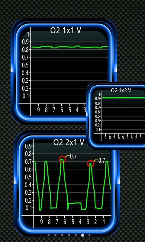
Aquanaut.... saw your post so I ran out and started testing. I set a graph for bank 1 and another graph for bank 2. On idle, Bank 2 which I am NOT getting the errors for was giving me real-time of a line bouncing between .1 and .7 but bank 1 was flat-lining at .5! Pushing up the RPM's had little effect on bank 2 but bank 1 would jump up to .9 and flat-line at .9! Any insight as a result of this test? Any idea on other tests I should run? Appreciate any 'hope' you could give me....
#17
02-09-2012, 08:45 PM
First, make sure you were looking at both B1S1 and B2S1, not B1S1 and B1S2. The sensor after the converter (B_S2) will tend to be a flat line as you described if the catalytic converter is working.
If you're positive that you were looking at both S1 sensors, then try unplugging B1S1 and see if you get the same results on the graph. You may get an additional code related to the B1S1 heater circuit. If the graph still looks the same, and since you've swapped sensors and it remains on bank 1, it would sound like you have a wiring issue for B1S1.
-Rod
#18
02-09-2012, 08:51 PM
Join Date: Feb 2012
Posts: 23
Likes: 0
Received 0 Likes
on
0 Posts
I will try that first thing in the AM... almost positive I was graphed out to sensor 1 on both banks.... next question is does results returned by an O2 sensor have any influence on the gas/air mixture as I am having issues with almost stalling and actually stalling when I apply the brake and go from Park or Neutral into Rev or Drive.
#19
02-09-2012, 09:34 PM
Yes, particularly the sensor 1 sensors are used by the PCM to adjust the air/fuel ratio by altering the fuel injector pulse width. If the O2 sensor reads that the mixture is rich, the PCM will use that data to reduce the pulse width. If the O2 sensor reads lean, the PCM will increase the injector pulse width. There is a limit on how far the PCM will alter the pulse width, and to get an idea what the PCM is doing with the pulse width, use you new toy (scan tool) to monitor the short term and long term fuel trim values. A positive number indicates that the PCM is increasing the pulse width, a negative number indicates a shorter pulse width. If I recall correctly, Ford expects these numbers to be less than an absolute value of 15% (or is it 25%?). Anything higher than that indicates an issue that needs to be fixed.
Of course there are also upstream issues that can cause "bad" readings on the O2, but generally those "bad" readings would not be a flatline at 0.5V (indicating a near stoichiometric perfect, 0.45V, mixture)
-Rod
Of course there are also upstream issues that can cause "bad" readings on the O2, but generally those "bad" readings would not be a flatline at 0.5V (indicating a near stoichiometric perfect, 0.45V, mixture)
-Rod
#20
02-09-2012, 09:48 PM
Join Date: Feb 2012
Posts: 23
Likes: 0
Received 0 Likes
on
0 Posts
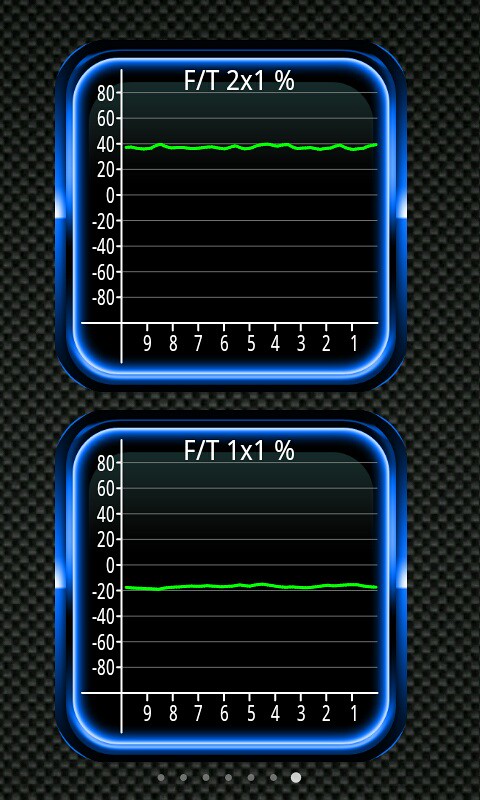
Double checked and I was running my graph on the correct sensors. Did this by adding a third graph for bank 1 sensor 2 and it was flat as well but a point or so higher. I actually ran two more graphs on another page for the fuel trim on both banks and got a fairly stead -20 on F/T bank 1 and a fairly steady +40 on bank 2. Next question is if it is a bad wiring to sensor 1 bank 1, would this be an issue with the voltage coming from the PCM or is the voltage being sent being sent from something else? Would it even be a "wrong sending voltage" scenario? Thanks guys!
#21
02-09-2012, 10:42 PM
Join Date: Feb 2012
Posts: 23
Likes: 0
Received 0 Likes
on
0 Posts
#22
02-10-2012, 01:41 AM
Cargo Master
Your last screen on the last post shows that you have an issue with bank1, bank2 displays the V readings switching as required.
When taking these readings the CPU must be in closed loop and the ECT>170*.
Values should be recorded at idle and at a steady 2000rpm with Tranny in N, both sets Should provide good switching and LTFT as close to 0 as possible. The CPU will normally fault when the LTFT exceeds 25% +/-, and the injectors may not compensate >15%+/-.......
The CPU is recording rich on sensor 1, (.8v)flat lined, so first look for chafed/pinched wiring or an injector stuck open..... Philip
#23
02-10-2012, 01:56 AM
Cargo Master
Follow-up on my other post.....
Do a full fuel system test, this includes pump running, static bleed down, FPR, and injectors......
The value returned on the B1S2 is disturbing as the should hold at nominal .45v +/-,
the high reading indicates a very rich mixture exiting the CAT. Either the CAT is dead or is about to shortly melt...... Philip
#24
02-10-2012, 06:49 AM
One of my "cheat sheets" for interpreting oxygen sensor data includes this quote from Kevin Caple, "A good catalytic converter can store a lot of oxygen. Since oxygen sensors read low voltage when they sense oxygen, and high voltage when there is a lack of oxygen, you should see a high number on the rear or post catalytic O2 sensors with a good converter because it has used up the oxygen cleaning the exhaust." If that's accurate, the reading above for sensor 2 should be okay and suggest that the catalytic converter is functioning as it should.
The fuel trim numbers definitely show that something is wrong, almost like a severe vacuum leak on bank 2 and a stuck open injector on bank 1.
-Rod
The fuel trim numbers definitely show that something is wrong, almost like a severe vacuum leak on bank 2 and a stuck open injector on bank 1.
-Rod
#25
02-10-2012, 08:22 AM
Join Date: Feb 2012
Posts: 23
Likes: 0
Received 0 Likes
on
0 Posts
Well one of my previous attempts was to replace the intake manifold gasket rings and while I was at it I swapped out the injectors from bank one to bank two and still have the bank one codes so we can rule out it being an injector. My ECT was nowhere near 170 as I had just run out and started it up to try graphing out my O2 sensors as recomended. I'll run everything I can this AM and post the results. Really appreciate your input on this guys!
EDIT
When I say rule out injector I mean the injector itself not the wiring as was suggested above.
EDIT
When I say rule out injector I mean the injector itself not the wiring as was suggested above.
#26
02-10-2012, 11:13 AM
Cargo Master
If you can access the FI plugs disconnect them and check for a stray ground running towards the CPU/PCM... K/Off.
The CPU supplies 12vdc common to all FI, then applies a timed ground (Pulse)to fire the FI.
A DVOM will be sufficient, a scope or Logic probe (pulse setting) also.....
Alternate test, run vehicle and disconnect one FI at a time, while monitoring the O2. The reading will fall to neutral when the offender is disconnected. This may set some miss fire codes but that is OK!........
You may also be lucky with a Mechanics stethoscope, listening directly to the injector.....should hear a clear definitive click on god FI ......Philip
NOTE: DO NOT apply direct 12vdc or a direct ground to the FI.. (NO HOT WIRE)
#27
02-10-2012, 11:42 AM
Join Date: Feb 2012
Posts: 23
Likes: 0
Received 0 Likes
on
0 Posts
Here are some reults:
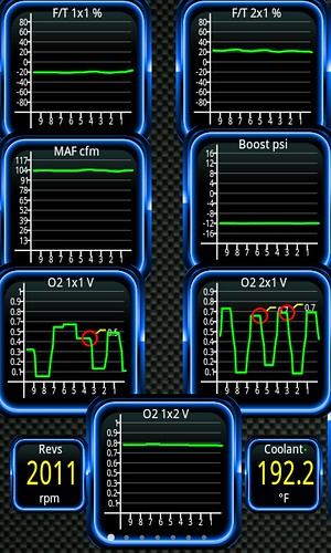
At 2000 RPM showing:
1)Fuel Trims Bank 1 & 2 Sens 1
2)MAF and VAC/Boost
3)O2 Bank 1 & 2 Sensor 1
4)RPM O2 Bank1Sens2, CoolTemp
At Idle (764):
1)Fuel Trims Bank 1 & 2 Sens 1
2)MAF and VAC/Boost
3)O2 Bank 1 & 2 Sensor 1
4)RPM O2 Bank1Sens2, CoolTemp
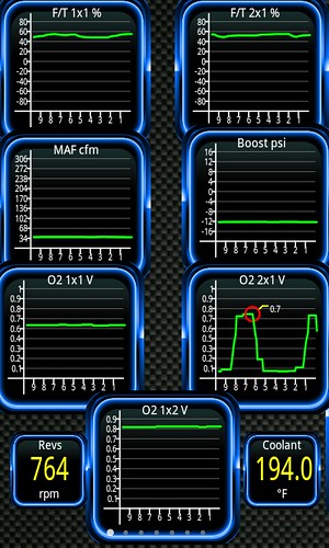
Anybody see something that jumps out at them other than O2 bank 1 sensor 1 seems to have better reading when at 2000 RPM and flats at idle?
I'll get to the next round of recommendations next.
At 2000 RPM showing:
1)Fuel Trims Bank 1 & 2 Sens 1
2)MAF and VAC/Boost
3)O2 Bank 1 & 2 Sensor 1
4)RPM O2 Bank1Sens2, CoolTemp
At Idle (764):
1)Fuel Trims Bank 1 & 2 Sens 1
2)MAF and VAC/Boost
3)O2 Bank 1 & 2 Sensor 1
4)RPM O2 Bank1Sens2, CoolTemp
Anybody see something that jumps out at them other than O2 bank 1 sensor 1 seems to have better reading when at 2000 RPM and flats at idle?
I'll get to the next round of recommendations next.
#28
02-10-2012, 11:46 AM
Join Date: Feb 2012
Posts: 23
Likes: 0
Received 0 Likes
on
0 Posts
#29
02-10-2012, 12:37 PM
Cargo Master
Aquanaut.... loving your recomendation! It's a bitch to get your hands in there but I'll find a way. Then when I run with the culprit unplugged I'll see my O2 B1S1 with better readings.... now why didn't I think of that other than I'm pulling my hair out! Thanks!
#30
02-10-2012, 02:14 PM
Join Date: Feb 2012
Posts: 23
Likes: 0
Received 0 Likes
on
0 Posts
OK... tried the "unplug one injector at a time" and got some results. #1 was the one that must have been throwing the code as it was the only one that while unplugged didn't return the code. Now I was aware I would see some codes thrown while having an injector unplugged such as "Injector # X..." codes but I wasn't aware that I would be seeing a "P0174 Lean bank 2" while I had an injector on Bank 1 unplugged... is that normal?
Next question... doubting it is the injector itself at this injector was on the other Bank the other day and didn't give me a bank 2 code.... what should I be looking at now? Metering the wiring to injector #1? What am I looking for? I will search for the proper testing/voltage but if anyone knows off hand.... as always it would be appreciated!!!
Next question... doubting it is the injector itself at this injector was on the other Bank the other day and didn't give me a bank 2 code.... what should I be looking at now? Metering the wiring to injector #1? What am I looking for? I will search for the proper testing/voltage but if anyone knows off hand.... as always it would be appreciated!!!

