wiper motor wiring
#1
 01-25-2012, 03:03 PM


Join Date: Jun 2011
Posts: 52
Likes: 0
Received 0 Likes
on
0 Posts
wiper motor wiring
well i committed a classic error. when i disassembled my 52 f3 i forgot to mark the wires connecting the wiper switch to the wiper motor. the switch is original with four wires comming out of it. the wiper motor has three wires in a line. i have tried using a ground wire and hot lead connecting them to the three wiper motor wires in many combinations. the motor is a six volt and the hot lead comes from a step down. the ground is to a bolt in the firewall (it will ground a tester light). can anyone tell me how to hook up this bugger. and yes i did mark every other wire during disassembly. hey you got to forget something. thanks
#3
01-25-2012, 03:34 PM

Join Date: Jan 2012
Location: Western Nebraska
Posts: 98
Likes: 0
Received 0 Likes
on
0 Posts
#4
01-25-2012, 03:34 PM
I just checked my shop manual and the electric wipers on the '51-'52 trucks is about the only thing that it doesn't show a schematic for. I do remember that the way it's wired is a little weird compared to more modern setups. I can still help you out, though, if no one else can and you can wait a couple hours. I've got a complete original setup that I know works still all wired together out in the shop. I'm headed to a wrestling meet right now, but I'll pull it out of the attic and take some pics of what goes where when I get back.
#5
01-25-2012, 04:00 PM

Lead Driver
The motor gets its ground from the frame. All three wires from the switch to the motor are, at one time or another, hot. The other wire on the switch goes to 6 volts.
Here's a diagram another kind FTE member sent me.
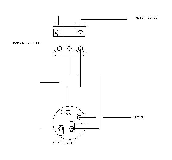
So none of the wires go to ground. The parking switch works by sending the same voltage (6vdc) to two of the terminal simultaneously, creating 0vdc difference in potential, effectively stopping the motor when the switch is in the OFF position. One of the leads (I think it's the middle one) receives slightly less than 6vdc for the slow speed. There must be a resistor in the switch.
My wipers did not work for several reasons, but the PO had wired the "power" lead to ground, so there was NEVER any power to the motor.
Here's a diagram another kind FTE member sent me.
So none of the wires go to ground. The parking switch works by sending the same voltage (6vdc) to two of the terminal simultaneously, creating 0vdc difference in potential, effectively stopping the motor when the switch is in the OFF position. One of the leads (I think it's the middle one) receives slightly less than 6vdc for the slow speed. There must be a resistor in the switch.
My wipers did not work for several reasons, but the PO had wired the "power" lead to ground, so there was NEVER any power to the motor.
#6
01-26-2012, 12:48 AM
I pulled mine down and had a look at it and it's wired just like Joe's drawing. There isn't a resistor in the switch - it's actually attached to the motor. The other thing that's a little different about this old tech stuff is that there is no braking circuit. Modern wipers incorporate a circuit into the switch and wiring that will basically short the motor leads together and halt the motor almost immediately when it hits the park switch. These original motors lacked that and they will coast a bit. How much depends upon the friction coefficient of the blades on the glass. Not a big issue, but they don't park reliably in the fully down position like modern wipers will. Sometimes they stop part way up the windshield and that can be annoying!
#7
01-31-2012, 06:43 PM
Join Date: Jun 2011
Posts: 52
Likes: 0
Received 0 Likes
on
0 Posts
Trending Topics
#8
05-26-2012, 02:46 PM
Fleet Owner

Thread
Thread Starter
Forum
Replies
Last Post
Redneck1465
1980 - 1986 Bullnose F100, F150 & Larger F-Series Trucks
7
11-09-2006 04:18 AM
ford55truck
1948 - 1956 F1, F100 & Larger F-Series Trucks
9
10-28-2004 11:20 PM