When you click on links to various merchants on this site and make a purchase, this can result in this site earning a commission. Affiliate programs and affiliations include, but are not limited to, the eBay Partner Network.
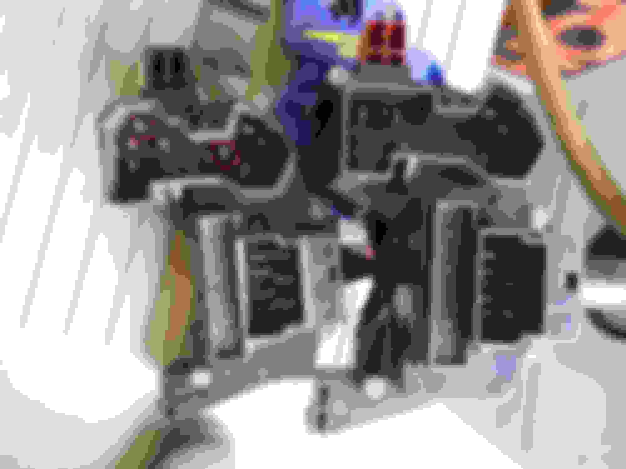
I did much the same, I wanted the wiring inside the A pillar so it is not going to be an issue with the trim. That's why I decided to do the LCM install while everything was out (steering column, e-brake pedal, instrument cluster and the big aluminum casting the 1992-97 trucks use to carry the steering column and left end of the dash.
At least you didn't have to mess with the side curtain or A pillar air bags!
I don't like that one bit, after doing testing with sodium azide initiators back in the '80's.
Before it got too miserably hot outside, I got some more done on the LCM installation. Got all the connections made on the left kick panel and switch areas and the wires pulled across next to the main harness in the dash. When I remove the dash to finish up the EATC install, I will tape it all in place.
I think this needs a door ajar switch to wake it up, or the door handle switches which I have to figure out and make something for. The Ford door ajar switches are in the latches and actuate when the latch is open even to the first catch. There were never any made for the older trucks that I can find. I decided to do what Chrysler did on the K-cars, a plunger switch at the rear of the doors in the B or C pillar area. After looking at what I had, I found a pair of Chevy G series van courtesy light switches, they are 3/8 - 24 thread and ground the circuit when extended.
Chevy courtesy light switch reset to maximum extension.
Gary, in answer to your question, yes, it works just fine, now I need to order 4 new ones so they will all be in good shape, the other three doors go to a "passenger door ajar" lead. If I can find a way to insert some "door ajar" labels in place of the 4WD stuff then I will have the warning lights.
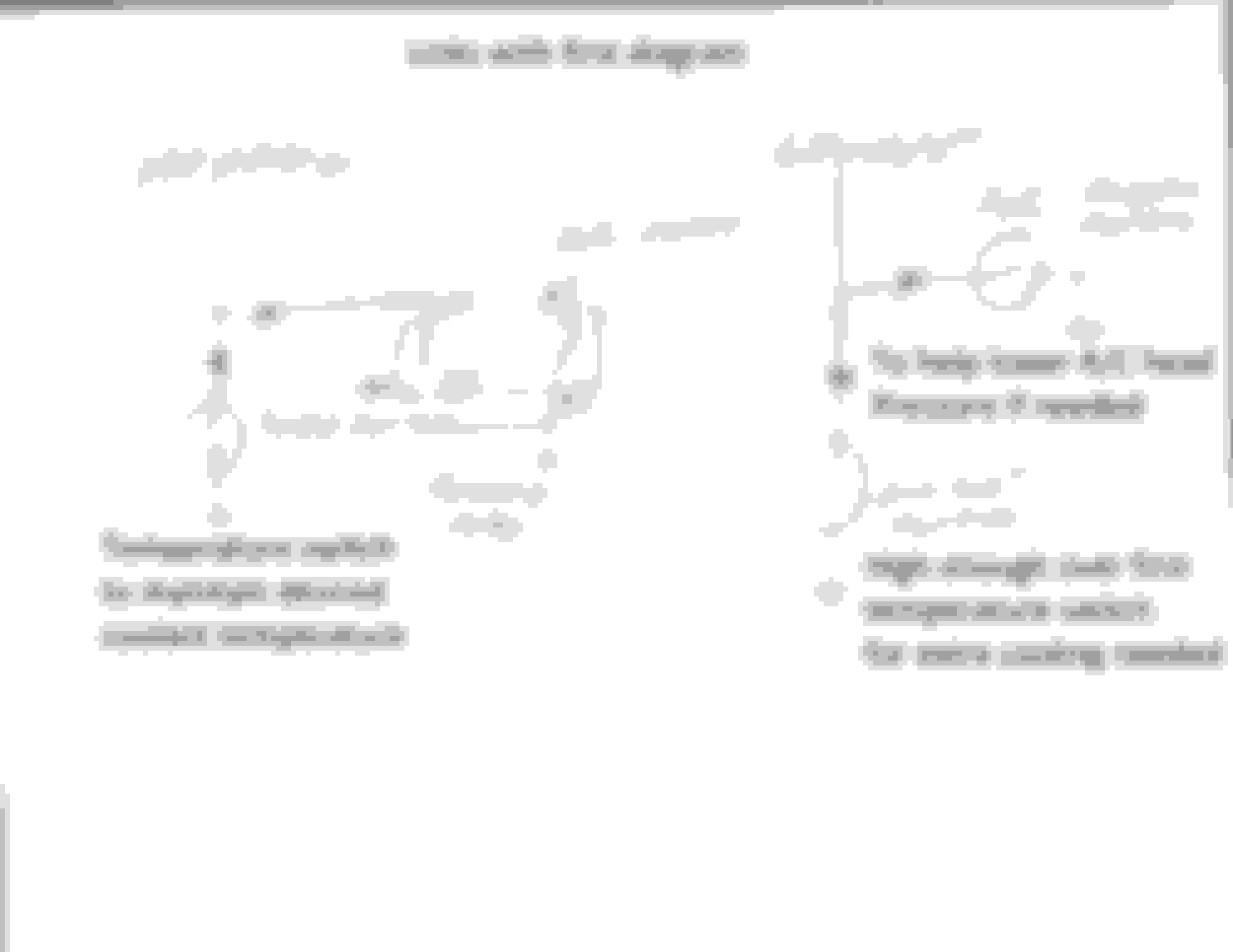
A few more pictures, first the combination switches. On the trucks, there are two separate flashers, one for hazard fed directly from the battery and on the 1992-97 trucks on the back side of the dashboard fuse block, and the turn signal flasher fed by the ignition switch. On the vehicles with either a lighting control module or electronic flasher, there are 2 more terminals as the same flasher is used for both and the hazard switch selects the power source in addition to turning on the required lights.
Left switch is from a 1995 Lincoln Continental, right one is 1992-97 pickup. Terminals circled in red are the different ones.
Interestingly enough, Rock Auto and some others list a switch for 1996/7 trucks (OBS bodies) with "electronic flasher". I took a Taurus switch with a bad wiper section and put the lever from an extra truck one in it.
Now that I no longer need the mechanical flashers, but do need their power source, I took the wiring and spliced it together and used the old hazard/turn flasher inputs for the two power sources for the new switch. I then took an extra set of the hazard and turn flasher inputs and used them for the power and flasher return circuits.
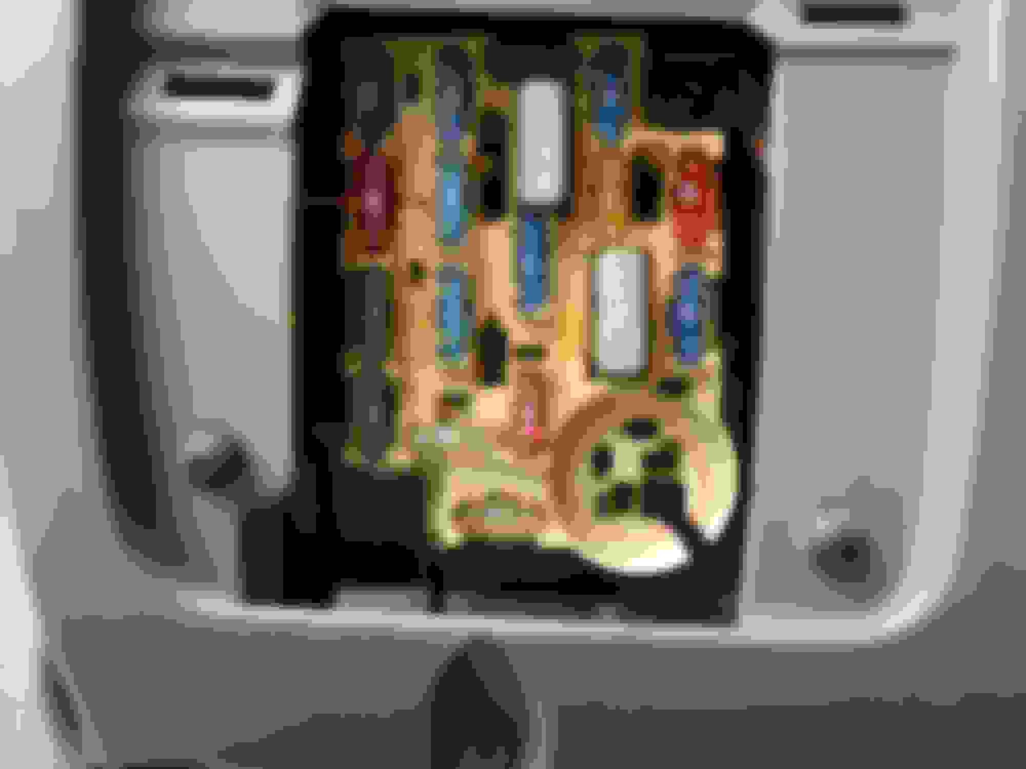
Two items, 10 amp fuse is in a diesel only slot, but provides constant 12V for the electronic modules. Circled location was the turn flasher location, hazard was behind it on the back side.
The LCM is now almost completely wired, I need passenger door ajar wiring and some lights. Switch needs a little refinement, but fits in the correct location.
I integrated some of that 90s stuff into my 86 Tempo, the JBL Audio stuff from the mid-90s Taurii, I tapped into an unused circuit breaker setup for power seats (or some such) which I didn't have.
There was an install kit put out by some aftermarket company that made the fit & finish look really good, and it sounded lots better than the old, almost-tube-driven thing with a mechanical tuner you operated with a ****.
Chris, I did a similar with my Taurus, installed a 2004 CD6 unit in it.
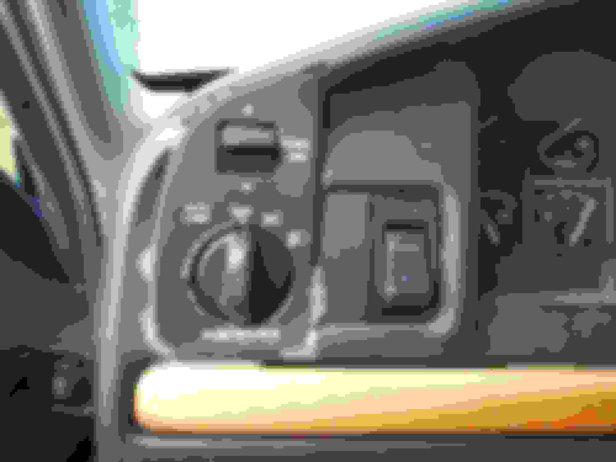
Since it got dark enough here, I tried out the automatic headlights. Notice the switch is in the "Auto Lamp" mode and headlights and dash lights are on. I think I need to have a talk with AutoZone on the battery, it dropped pretty low while I was working on it, and almost didn't start later.
My brother was complaining about one of those headlight auto-shutoff things on one of the Taurii but I never saw the alleged behavior myself so I hafta wonder.
Mine sometimes is temperature or humidity affected, the PO said it did it for him too. He is an electronics guy and had an explanation as to why, it has to do with the sensors that were used.
Judging by the "it grounds either relay" I'd assume the low relay drops out when high comes in.
Anyway, I understand. Standard relay for Low and Start, and HD relay for High. Thanks for the explanation.
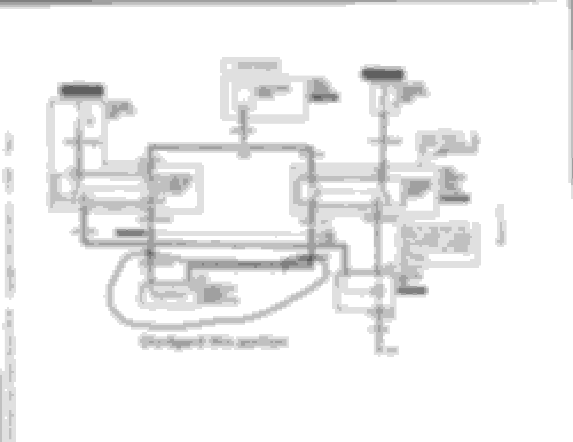
Gary, I played with a Thunderbird fan today, a little bit smaller version of the Crown Victoria unit. Low speed by itself = low speed, high speed by itself = high speed, low and high together = high speed. I can't run it full on high as my nice regulated DC power supply only puts out 25 amps. There was no change in current draw with or without the low speed wire connected while the high speed was connected. Based on that, the low speed relay can stay on. I will work up a diagram for you later, but basically it used two temperature switches, one for on-off low, and a second for overheat. A/C would bring low fan on with the compressor, and a high pressure switch for high fan if needed.
This is the 1999 Crown Victoria fan circuits with the PCM portion marked disregard.
This is the continuation, one more Bosch relay, 4 diodes and 3 switches.
You might want to grab the underhood power center and high current relay center from the car you get the fan out of. That will give you the wiring and fuses/breakers for that system and what you want to do anyway.
Temperature switch, say on at 185� off at 175�, overheat maybe 200� A/C high pressure is usually (on later vehicles) a double pole single throw, one NC, one NO, NC opens to shut the compressor off, NO closes to turn on the fan. There is a bit of range between fan on and compressor off. Diodes are to prevent cross feeding, but you may not need them.
 07-13-2016, 07:22 PM