
2.5kW inverter, RF equipment, Rack install (Note: Many images to load)
#1
 11-12-2011, 01:49 AM

The purpose of this thread is for me to document my truck projects so I can link to it later on when others ask questions. It is also open to discussion of course if my fellow users here think they would have done so differently.
This post will be updated accordingly as relevant (provided that edit functions do not expire on these forums).
As noted in the title of this thread, the usual items that I add to my trucks are:
2500W Sine Wave Power Inverter
Introduction and Rationale
Most people today are familiar with the applications of a solid state DC to AC power inverter, being to operate electronic or electrical devices designed for line voltage, normally 120VAC 60Hz.
Under normal circumstances, I use a power inverter to charge or operate computers, test equipment, and soldering irons. During power outage situations, I have operated network infrastructure equipment (telephone system, core network switch and routing devices) at a medium sized office off a 1kW modified square wave inverter. However, equipment does not run efficiently on modified square wave, hence the selection of a sine wave model.
I would like to clarify that my usage of a power inverter is not intended to replace the functions of a traditional moving field, engine driven electrical generator. It is intended as a convenience power source. The inefficiencies of an inverter installed as part of a vehicle's electrical system are far too great to consider this as a stationary power source when compared to a dedicated engine generator. Consider the massive vehicle engine driving a small belt driven alternator (auxiliary load) rectifying AC to DC, and then converted from DC to AC.
I own a small 15kW, split phase 1800RPM towable diesel generator set, but of course it depends on me actually having it with me since it is unlikely that I will just pull one around all the time 'just in case' for various reasons including but not limited to vehicle maneuverability, reduced vehicle fuel efficiency, and increased risk of theft. The inverter will be installed on the truck and is conveniently available.
Implementation
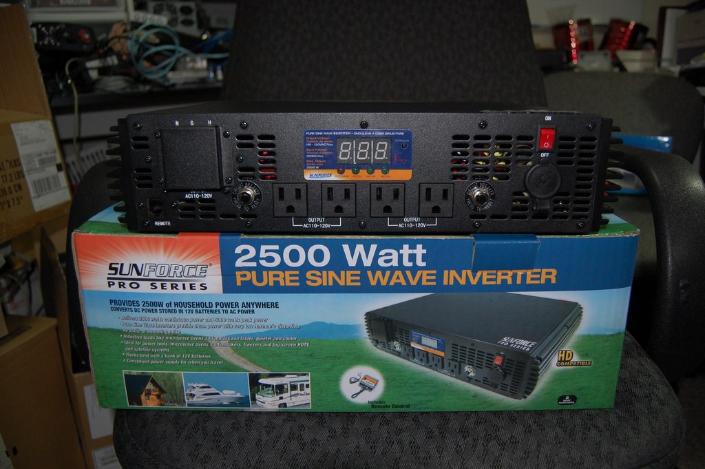
I ordered a SunForce 2500W Pure Sine Wave Inverter. In this application, the 2500W rating has been selected for its high surge capacity, and its price point in relation to a similar 1000W sine wave model inverter. I do not expect to be running close to maximum rated power on a long term basis.
In the past, I have always specified Xantrex brand power inverters and they have been of excellent build quality and operational stability. They are sold at a higher price point and are commonly used in RV applications. A comparable product would be a ProSine 1800, which runs from $800 to $1000 CAD. The SunForce I am using for this project cost $400 CAD. Throughout long-term use I will evaluate the differences, if any, between the brand name product and the lower cost product.
SunForce PSW 2500W compared to Xantrex MSW 1000W
The dataplate rates a maximum current draw of 250 amps on the DC side.
This model offers a terminal block for hard wiring devices.
Just to get an idea of internal build quality, I removed the side panels to observe the components.
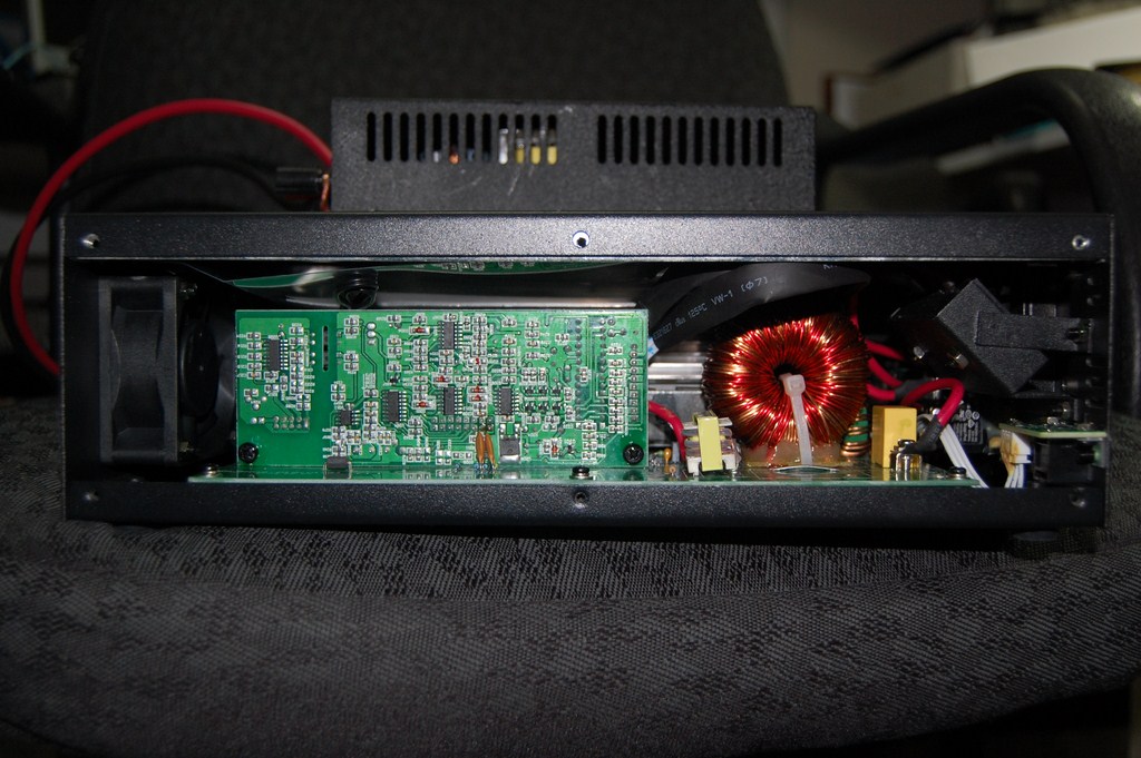
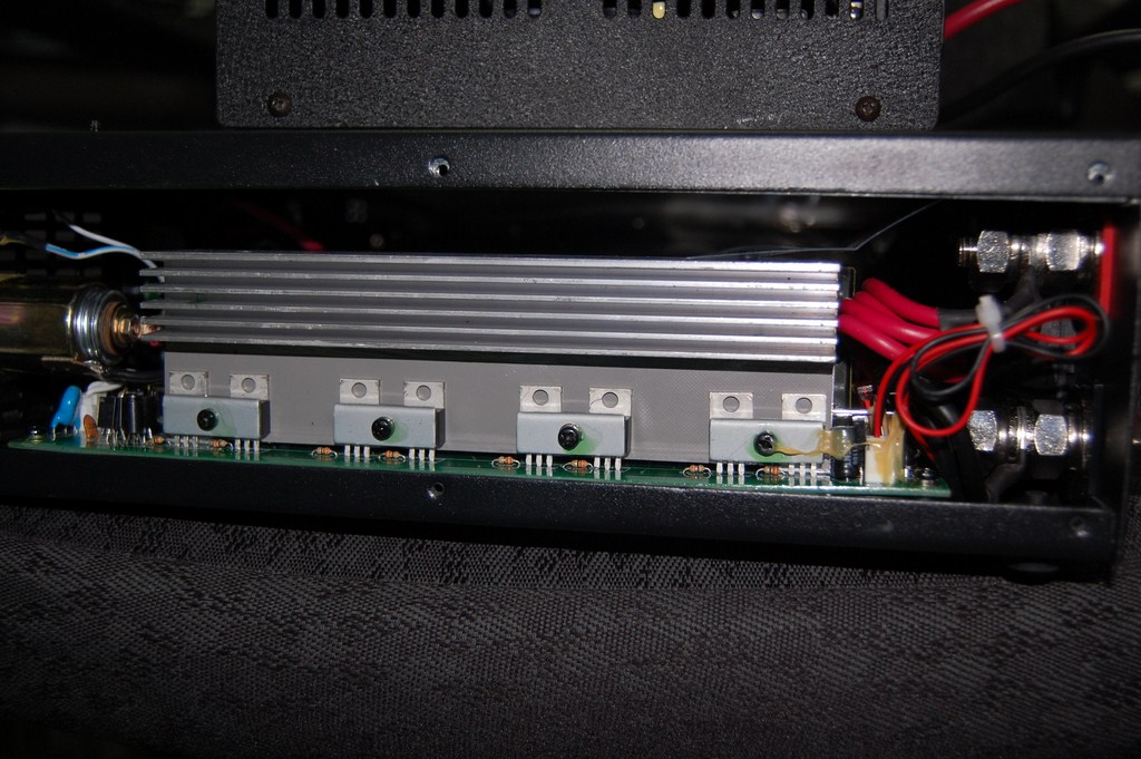
There are 4 banks of semiconductors attached to large heatsinks. (The other 3 are behind this one in the picture)
A power inverter can be seen as a big amplifier running at higher voltages and tuned to work only at one frequency.
On the right, the DC terminal posts are seen. Note the use of parallel runs of 10AWG for easier wire routing and flexibility within the limited space within the product.
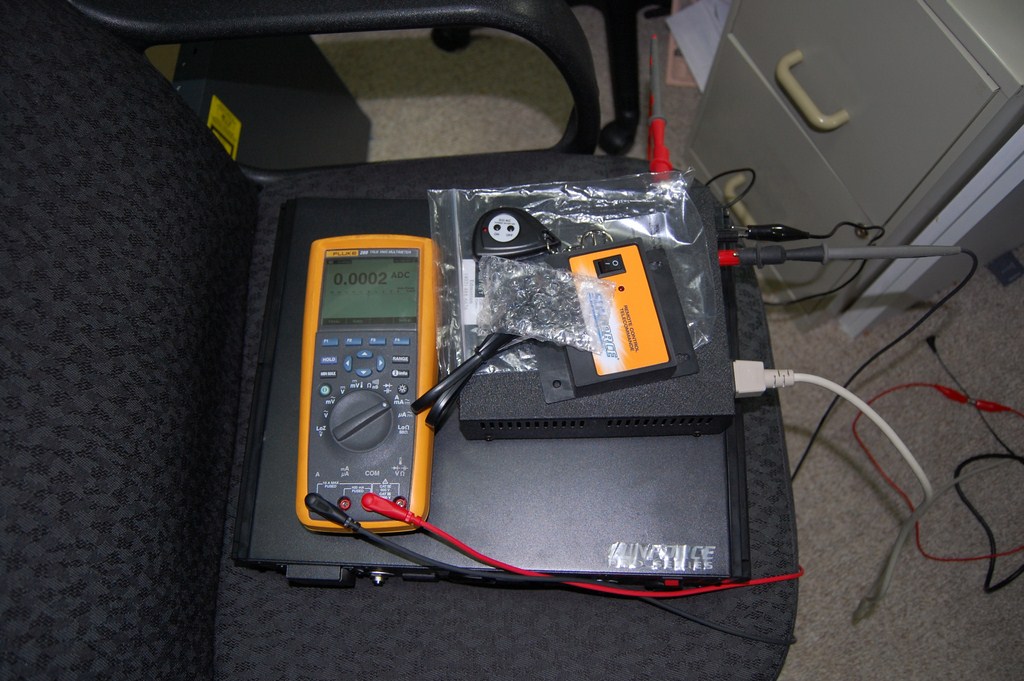
This inverter will have to be hard wired to the battery (most should if they're anything more than 400W). I considered using a high current DC-rated contactor with 12VDC coil winding as a positive disconnect device, however sourcing one was difficult and such a device would have been prohibitively expensive. I evaluated the parasitic current draw of the inverter in its 'off' state. This was evaluated without the use of the remote control receiver which is included with the product. I placed my meter in series with a regulated 13.8VDC 10A power supply (radio desktop power supply) for this test.
I decided that 200 microamps was negligible and would not discharge the battery, given the other stuff in the truck that operates on battery, and the transmission that likes to make meeping noises when the truck is shut off.
Now a note on cable sizing and ampacity. I selected 4AWG welding cable for this project due to availability, practicality, and cost. The ampacity of a cable is based partly on the wire insulation's ability to withstand heat and welding cable has thermoset sheathing with high temperature ratings. I've also used welding cable in its intended application running 170+ amps DC constant current with a jet rod without having the cable burst into flames. Therefore, I believe it is suitable for this task.
Furthermore, inverters are not dumb loads, they have inherent protection systems and monitor voltages and if too much energy is being dissipated as heat over the cable, there will be a voltage drop across the cable and it will be seen at the load end (inverter) end as a low voltage condition. The inverter will error out and shut off based on that.
Overkill is always a good thing, and you may instead choose to use 2/0 AWG wire or several parallel runs of a lower gauge. I would not argue with that practice.
In place of a disconnect contactor, a high current 2-pole connector was used. It is important to note that connectors are generally not designed for current breaking so it should only be connected or disconnected with no load. I did not want to be attaching the cables to equipment (battery or inverter) live with a wrench, lest I slip and drop it across the terminals.
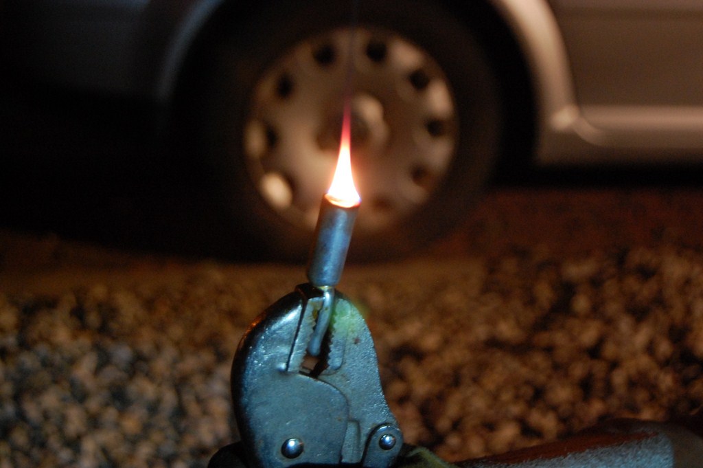
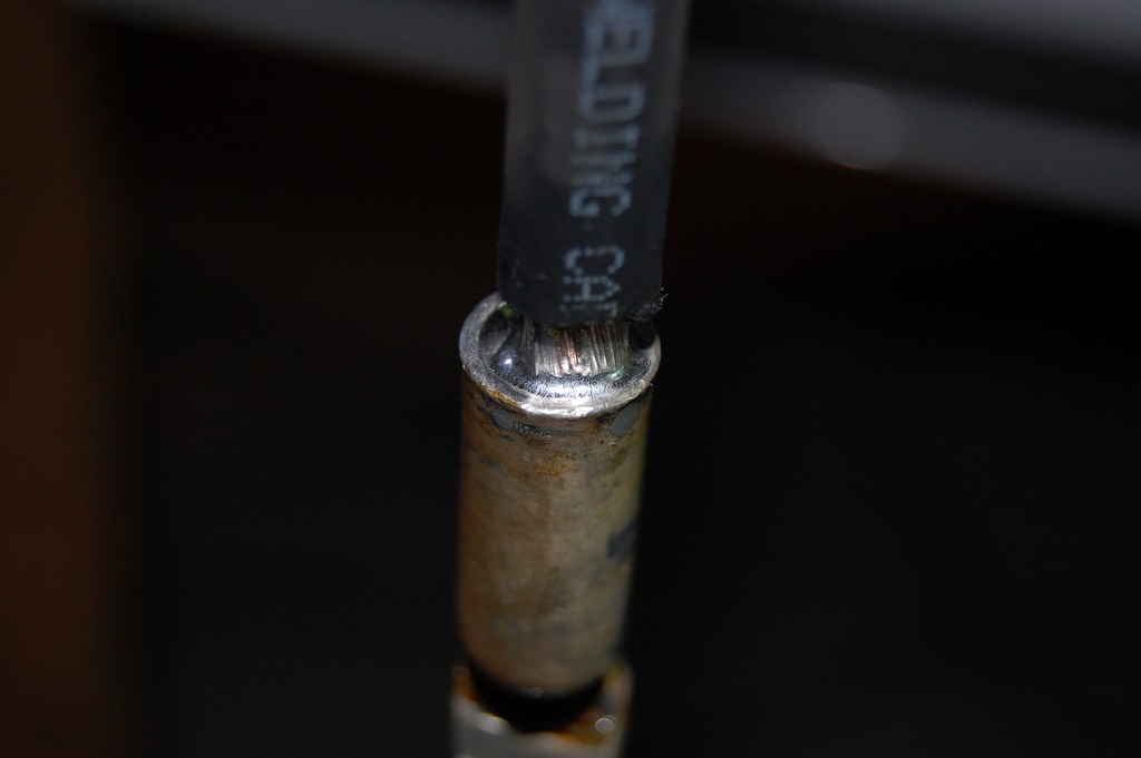
I soldered together a pigtail cable. The soldering was done with a blowtorch. This once again highlights the high temperature rating of thermoset insulation versus thermoplastic insulation which would rapidly burn off when exposed to a blowtorch flame. The connector lugs can also be crimped with a suitable crimping tool.
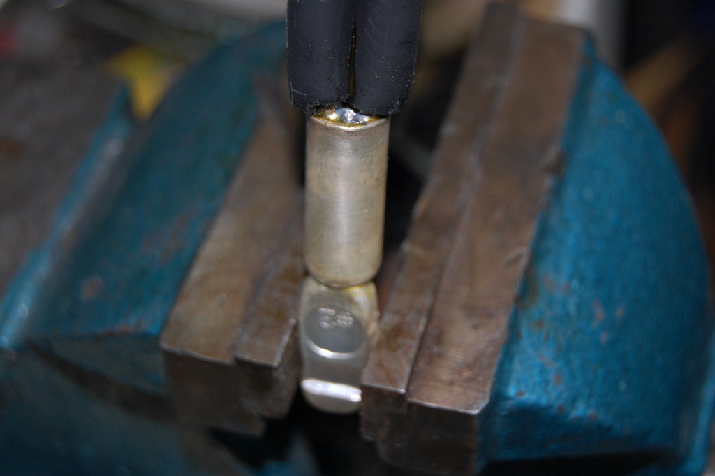
One end was terminated with the connector pin, the other terminated with a copper lug. A 12AWG line was used to tie the chassis ground (also ground pin on the AC side) to the negative terminal, being vehicle ground.
The connector I used was a clone of the Anderson PowerPole and is assembled (push until clicks) exactly like the brand name product. There are many variants of this. These are hermaphroditic connectors so the side doesn't matter.
Now onto the vehicle side of the project... the rest of the steps will be in an order that is easier for explanation purposes, but is not necessarily the actual order I did them in. Therefore some of the pictures will go between daytime and night time and it may seem weird.
I decided to place the inverter behind the back seat since there was no other feasible location for the device. There is insufficient space under seats for this due to the floor air vents. If you don't have the storage tray under the rear seats it might be able to go there but passengers may be prone to kicking it.
First step was to take out the "rat fur" (which is officially named the 'Ebony Ford NVH Enhanced Cab Back Panel W/Center Restraint - XLT & Above') and the C-pillar covers to make it easier to work in the area. The middle seat belt is unfastened with a thin object, like a finishing/picture hanging nail or a precision screwdriver.
The kick panels come off by pulling on them. Like most everything in vehicles these days, it's snap fit. This reveals a sort-of cable tray which is already quite crowded. I chose the driver's side because the passenger side of the vehicle is totally packed with wiring, since the PCM is located halfway in the middle of the firewall on that side.
I ran the control wiring first. More on the control side later.
I used cat5e, because I'm a telecom guy and I just have too much of this stuff. Possible alternatives on the control side are Low Voltage Thermostat (LVT) cable, lamp cord, speaker wire, or individual wires twisted together.
Control line run ends at under the dashboard.
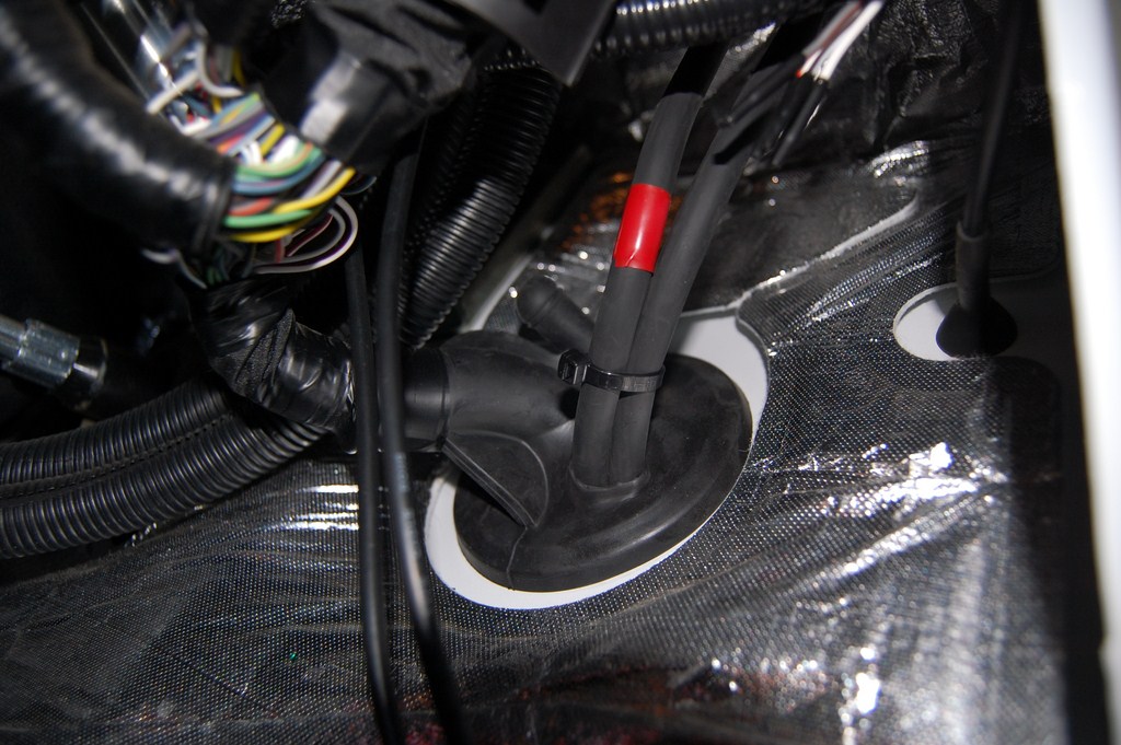
I pulled off the wheel well liner to get access to the firewall grommet. The crowded engine bay makes it very difficult to get to it from the top.
The removable cupholder inserts make convenient parts cups.
I ran the welding cable in the cable trough. If you chose to use 2/0 cable, it will probably not fit there and you will have to run the cable under the floor, or route it outside of the cab and run it inside the C-channel frame.
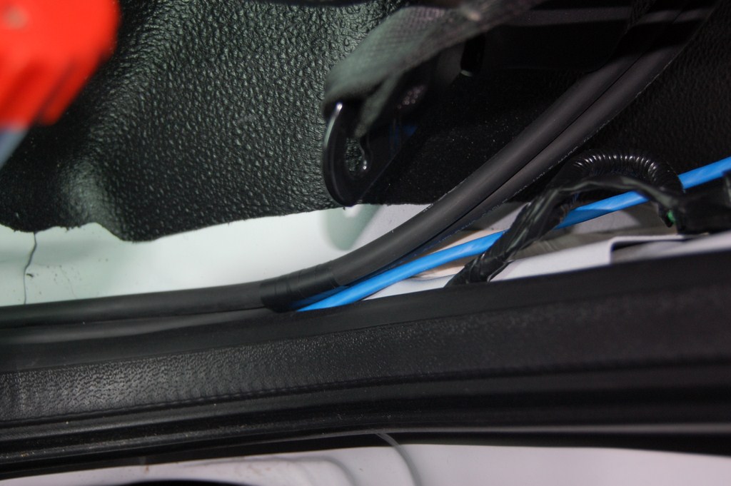
Poke it out through the grommet. Take care to not destroy the existing wiring harness that runs through it, because there are some duplicate wiring colours in there so it's going to be worse than trying to splice severed 50-pair phone line and wondering where the wire binder ribbon wrap went.
Now is a good time to run any other wires for other projects. I ran 2 coax runs for the radio antennas, documented later on.
Terminate the ends with the appropriate connectors. I soldered these ends as well with the propane blowtorch. As mentioned earlier, they can be crimped with the appropriate crimping tool as well.
Waiting for all the flux in the solder to burn up.
After this picture was taken the connector was wirebrushed clean to remove all the flux and other contaminants. Flux is a good insulator so make sure all the contacts are clean.
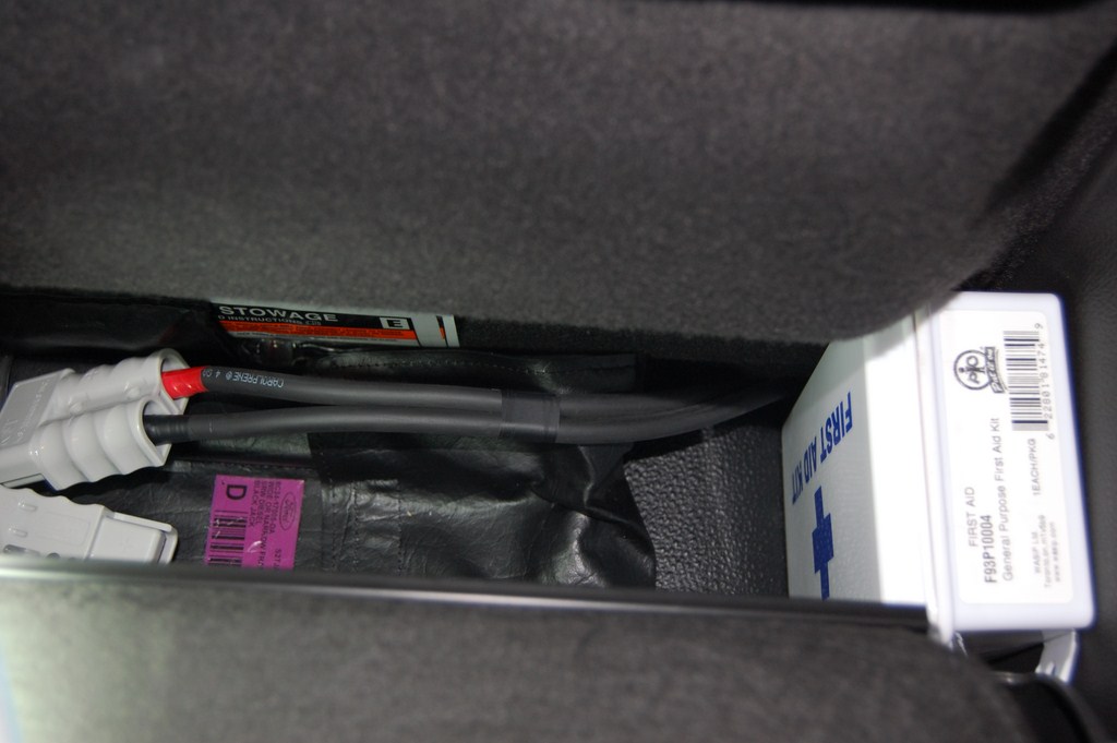
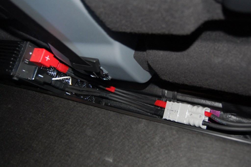
Replace cab back panel and C-pillar covers. At this point I assembled the DC side connector. Don't plug anything in yet!
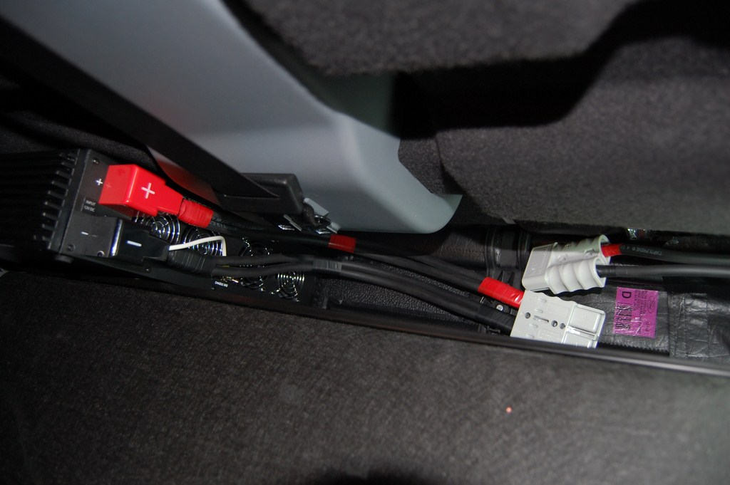
The cable routes nicely out of the gap in the C-pillar cover. And I can still fit my first aid kit in that corner.
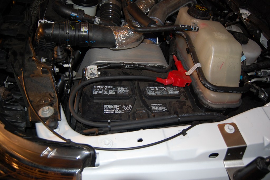
Terminate the engine bay side of the cable as appropriate (in this case, copper lugs). Ensure that the other end of the cable inside is NOT touching anything conductive. Check continuity between both cable runs and make absolutely sure that you have infinity ohms of resistance. Attach to the battery. Or hold on a second, a few more notes on best practices:
Ford recommends that on diesel engined vehicles with dual parallel batteries, you use the primary battery on the passenger side for electrical loads such as jump starting another vehicle. I have connected it to the secondary battery on the passenger side. The primary battery is hard to attach to due to the amount of other connections attached to it from factory installed electrical systems. Furthermore it results in a longer cable run and you have to take the long way around to avoid the engine components.
Standard electrical procedure specifies that a current interrupting device (circuit breaker, fuse) should be installed as close as possible to the power source to protect the wiring. Such a device will require some searching since you won't find it at a auto or hardware store and wholesale electrical distributors won't have high current DC rated circuit breakers. A store specializing in solar power systems would be your best bet. Perhaps a vehicle audio/entertainment systems installer may have such a thing kicking around. Marine supply shops may also have something similar, but we don't have those around here. I'm going to have to trust my own work.
Conversely, it is not normal practice to put breakers on huge telecom 48V battery banks which have more than 10 times the current capacity as your vehicle electrical system. (Electrical tape your wrenches!)
Also note that the factory parallel cable run between the batteries is not fused either.
Past that topic of potential internal controversy, check the polarity and voltage the other end and hook up the inverter.
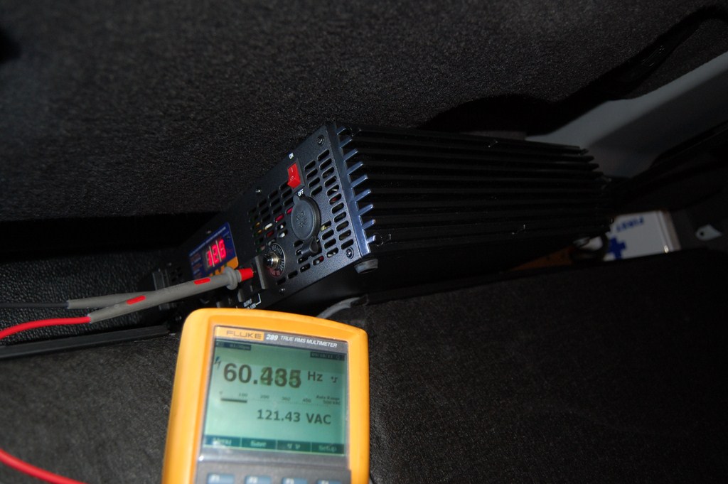
If all goes well, the inverter turns on and the AC side will be outputting the correct voltage at a frequency reasonably close to specification.
This is enough work for basic inverter operation, but I continued on to add a control line to an upfitter switch and wire up Battery Charge Protect (BCP) and Stationary Elevated Idle Control (SEIC) functions.
At this point, reassemble the kick panels and the wheel well if that was removed.
Upfitter Switch Control
Per Ford bulletin Q-180-A, a resistor value of 20,000 ohms results in a high idle of 1200RPM. While BCP functions do not depend on a specific resistor value, it does require A resistor in the circuit. In addition, I plan on wiring SEIC enable to another upfitter switch.
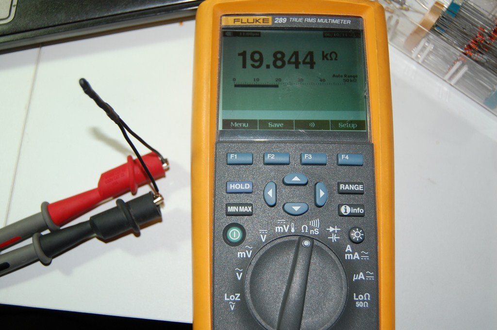
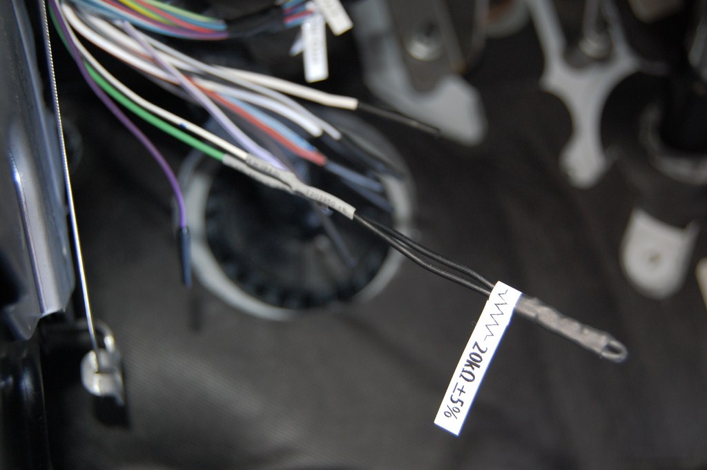
I added wire leads to and shrinkwrapped a 1/2 watt 20k ohm resistor since they tend to be fragile on their own.
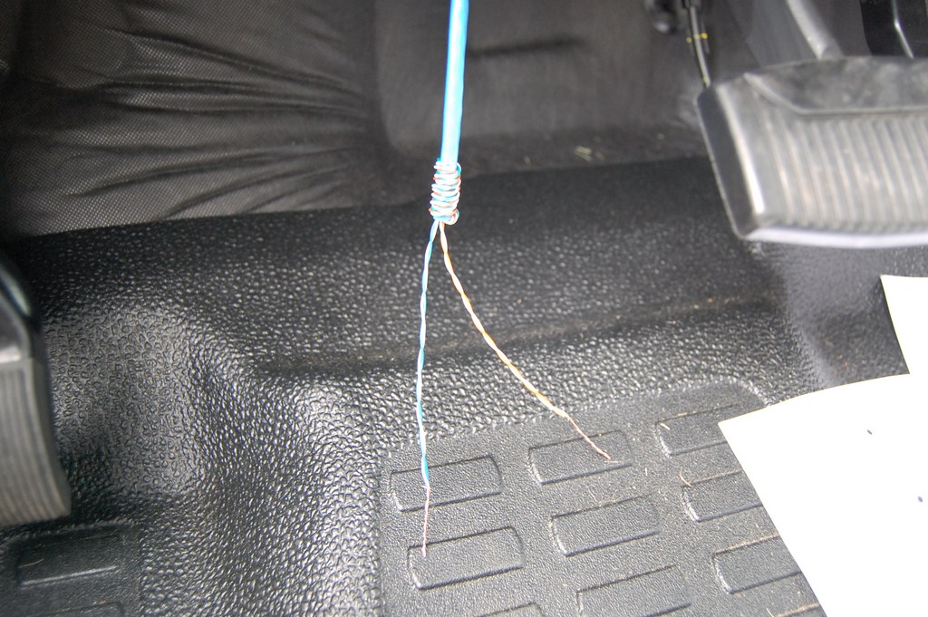
One side of the resistor goes to an accurately regulated 5 volt reference line from the PCM, White/Brown, the other to the PCM reference reading line, Green. The resistor that you add completes the voltage divider circuit, and the PCM reads the voltage drop across the resistor with a analog digital converter (ADC) to determine SEIC RPM.
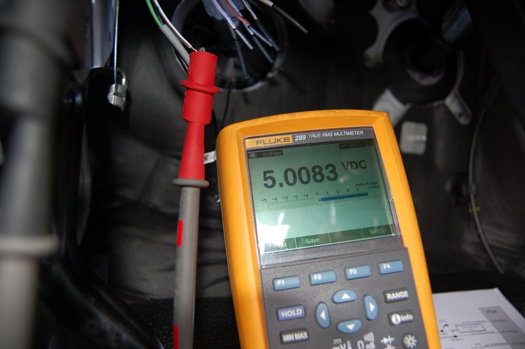
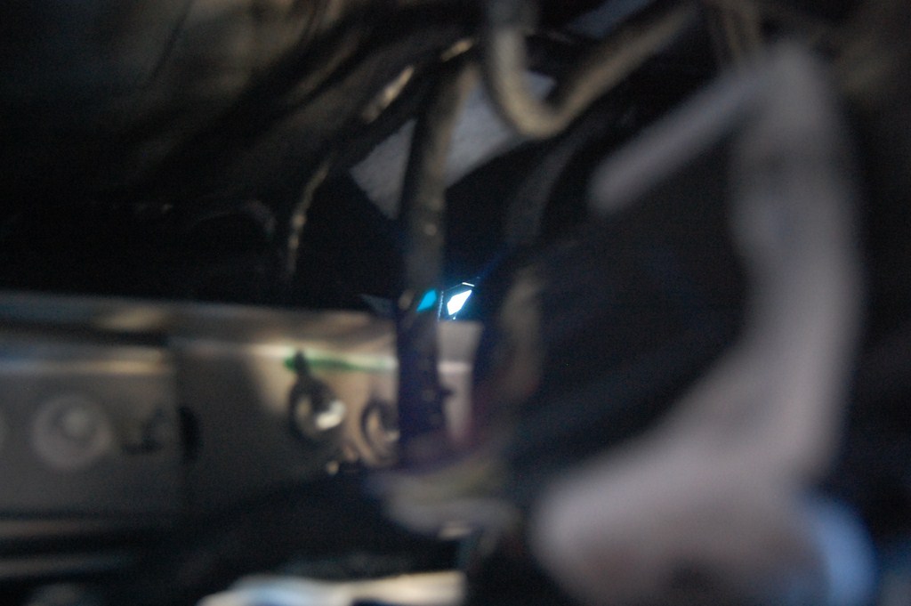
Here I am verifying that I have indeed found the 5V reference line.
Solder, shrinkwrap, label. I'm not going to mention the alternate methods of connecting wires.
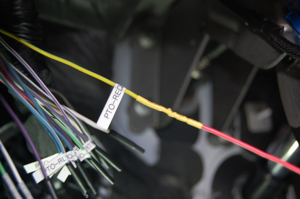
SEIC is easiest so I'll do that first. I selected AUX-3 for that purpose. The line for AUX-3, Violet/Green (on the harness behind the knee panel), supplies battery voltage to the PTO-REQ1 line, Yellow/Green.
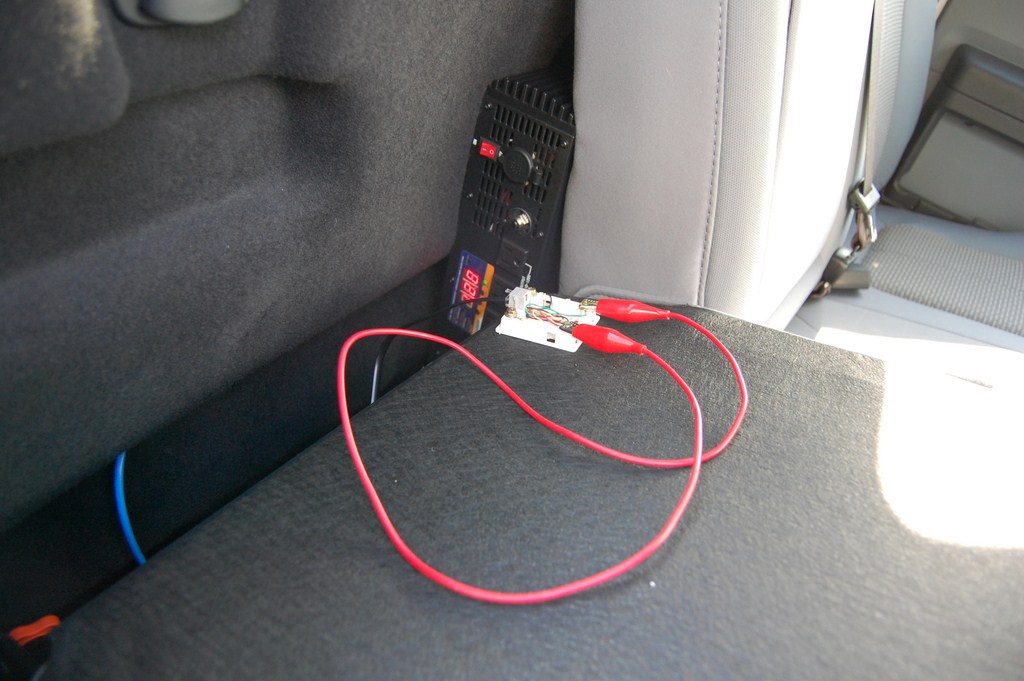
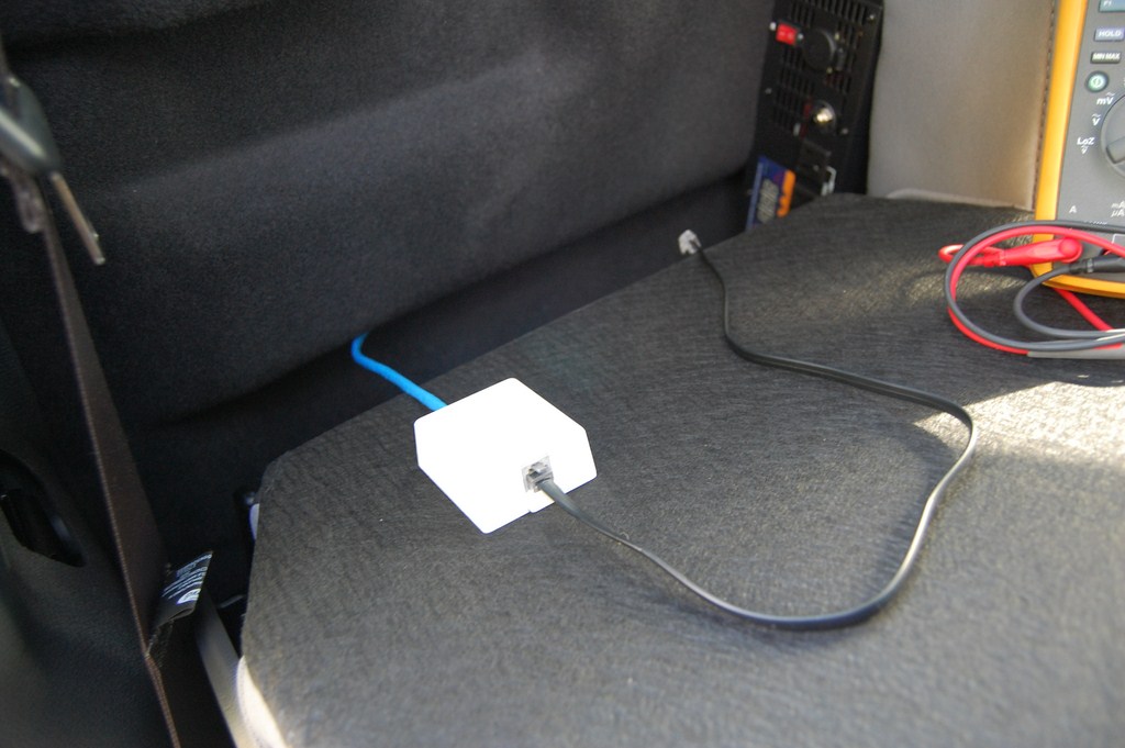
Let's go back to the inverter. This inverter was supplied with a RF remote control module that plugged into the front panel of the inverter with a 6P6C modular jack. In the phone world it's a RJ-25. Upon disassembly and inspection of the remote control receiver module, the module simply closes a contact between the first pair tip and ring (Also known as... middle of the connector, 6-position jack: pins 3 and 4, Standard colour code: White/Blue and Blue/White, Old colour code: Green and Red). Remember that this is only the case with my inverter and may not apply to other models. You may have to hack the case and splice into the power switch wires.
By jumpering over those 2 wires, the inverter turns on. (Note front panel switch is in the off position.)
I used a surface mount jack aka "biscuit jack". Yeah, phone guy. Actually I can't think of anything better to use in this situation.
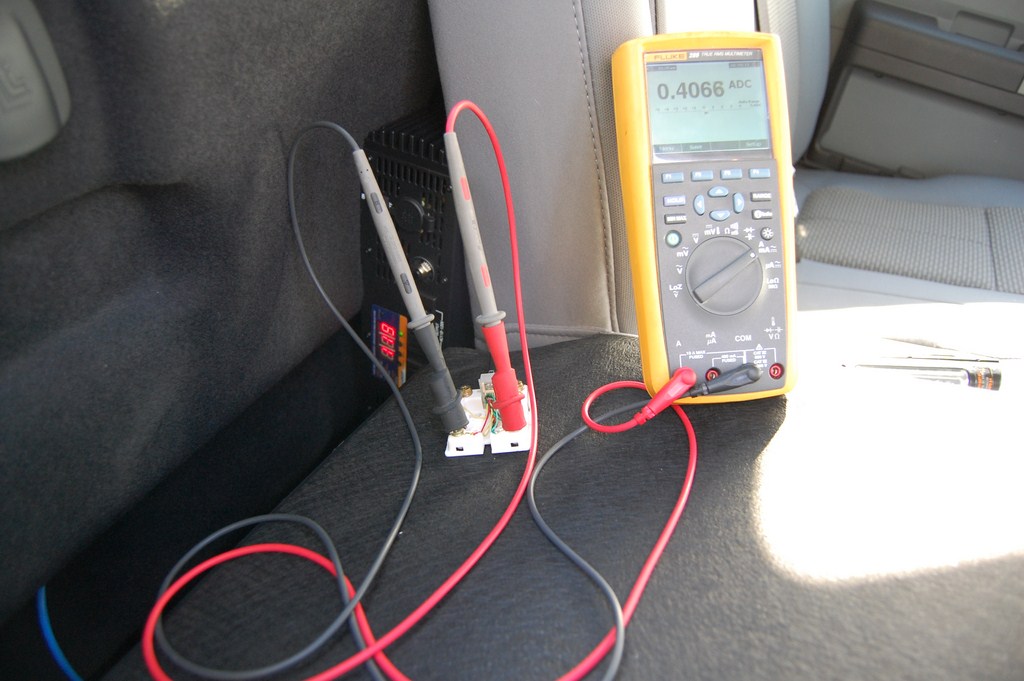
The control circuit is low current, but quantitatively, what does that mean?
It means 400 milliamps. Yes, the phone line and network cable will handle it.
Dig out the Cat5e line that was pulled earlier. I twinned the lines and used a pair for each side. This leaves 2 pairs free for future applications.
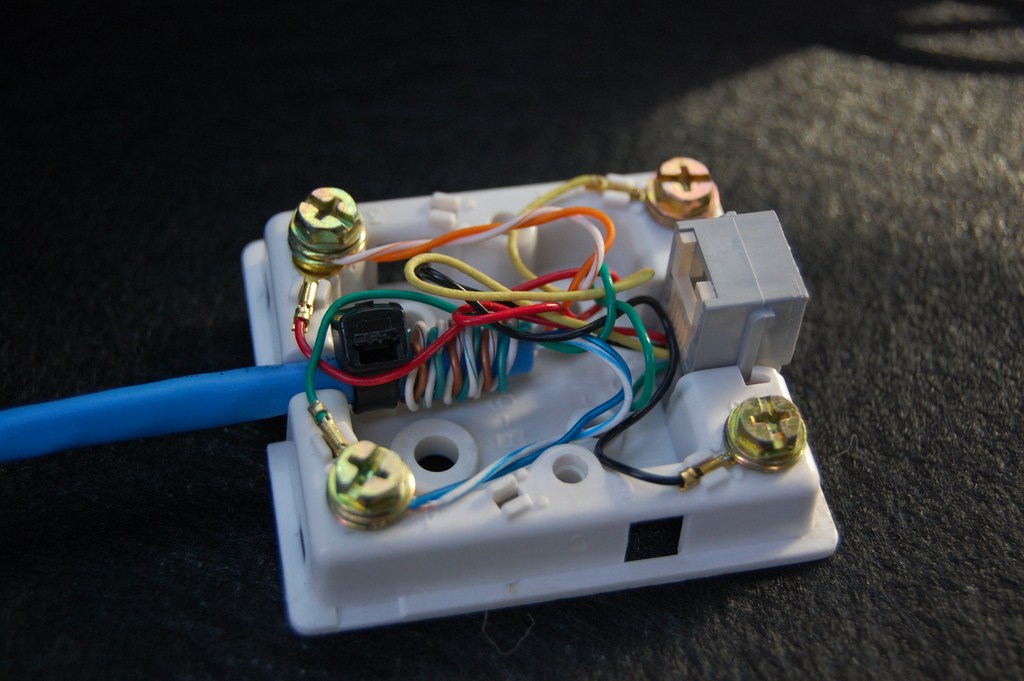
Close it up.
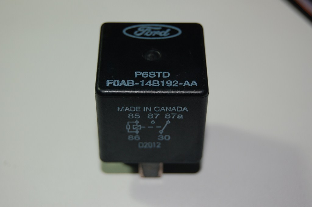
The upfitter switches control relays to supply 12VDC. Except I need dry contacts in this application. So, we will use another relay. I happen to have several boxes of new-old-stock Ford relays. (I actually use them on installations to wire up 70V overhead speaker paging systems onto phone systems and mute background music when the amplifier doesn't have a precedence feature. Pretty versatile.)
Ok, so the relay doesn't have to be Ford branded or Made in Canada or even have a normally closed contact or any high current rating, but it should have a 12VDC coil and a normally open contact.
Add wires to the relay. Or use a relay socket, if you have one kicking around.
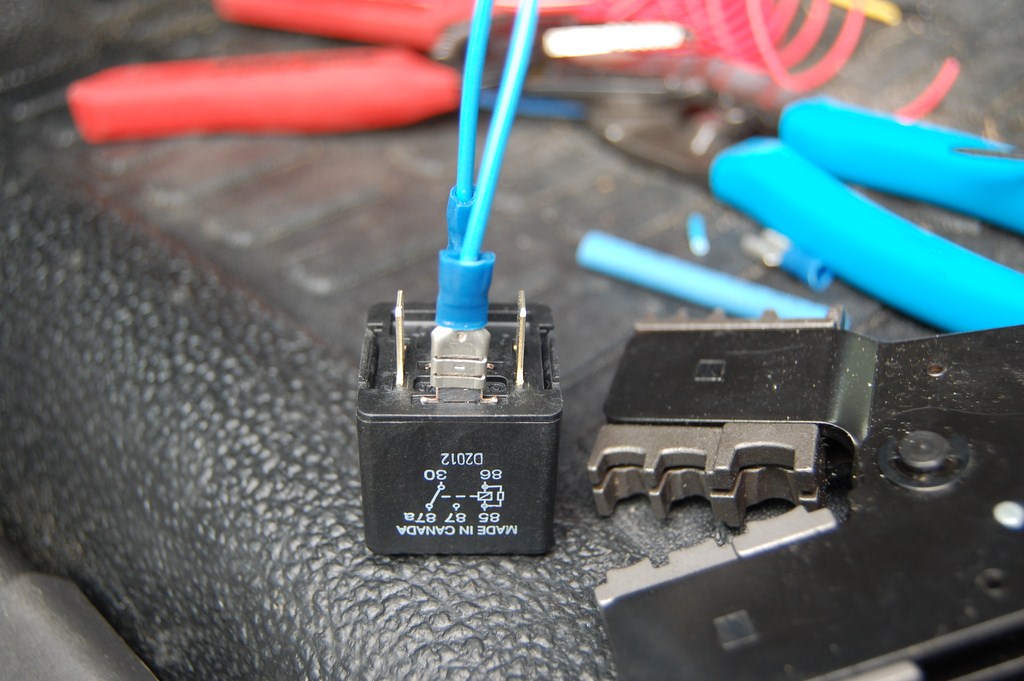
Find the other end of the Cat5e (or whatever cable was used). These 2 wires should go between the common and the normally open contact on the relay.
The desired upfitter switch (I selected Aux-4, Brown on the harness behind the knee panel) should be connected to one side of the relay coil, the other side of the relay coil is grounded. I wanted BCP to be enabled whenever the inverter was turned on via upfitter switch (which will only apply when the vehicle is parked with parking brake applied) so I also wired Aux-4 to the BCP-SW wire, Violet/Brown.
At this point, the inverter should be turning on when Aux-4 is turned on with the key ignition switch in Acc or On. If the engine is running and the vehicle is parked, you will hear the engine RPMs change a bit as BCP is enabled.
I also ran a light duty extension cord in the space between the two under-seat storage trays for convenient access by passengers. It tucks in to the space between the 60/40 seats when not in use.
Testing
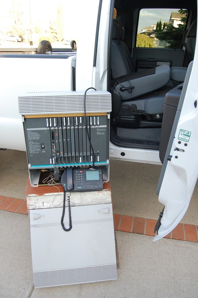
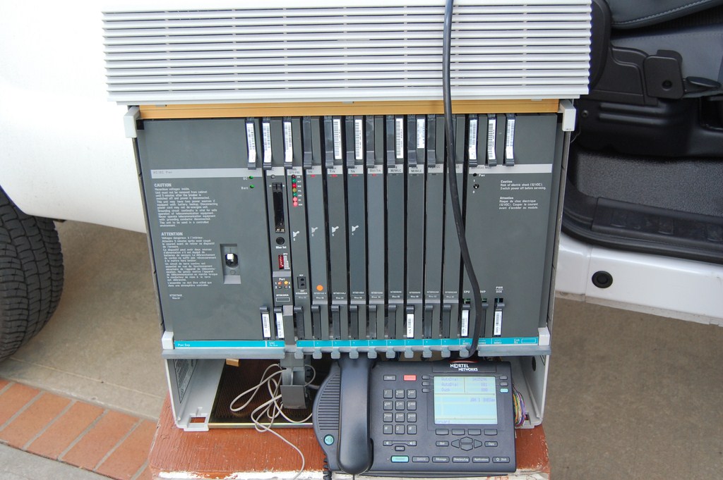
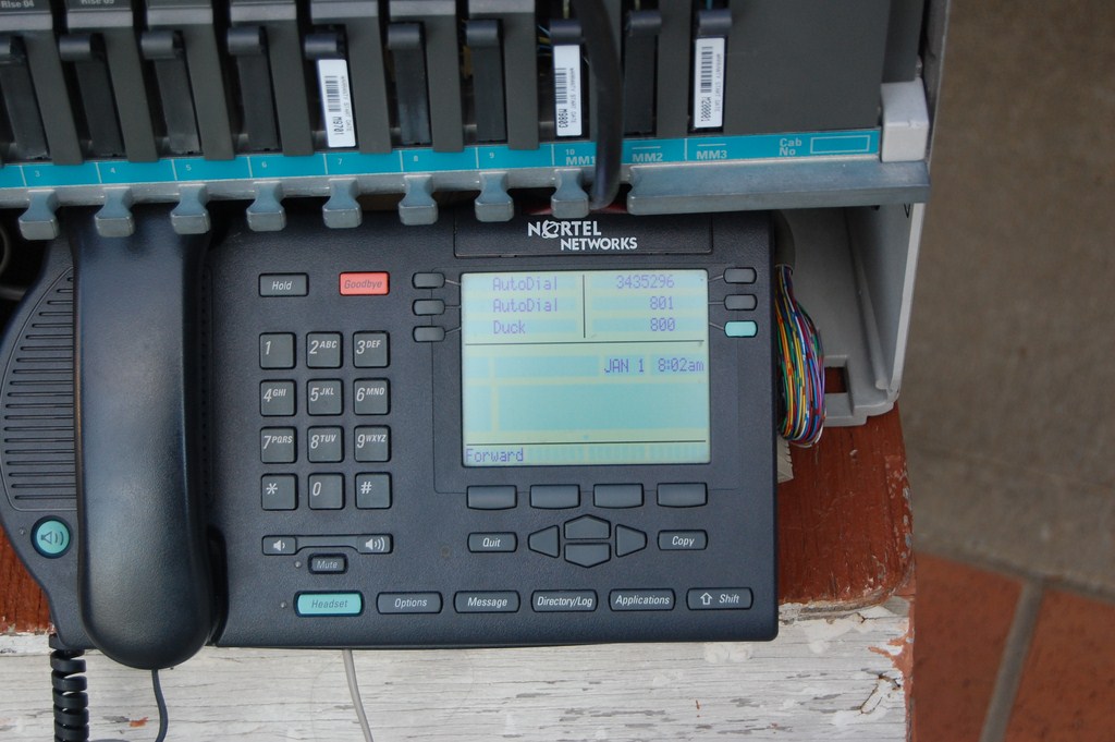
I tested the inverter by running a small telephone switch off it, a little Option 11c. It only pulls about 350 watts, especially with only 1 phone powered off it, so it's not much of a load test as it is a test of clean power. Power supplies hum like mad when they are running off noisy square wave power. They are quieter when running off this inverter. The best part is that the inverter never really runs its fans since most loads are not stressing the unit at all.
Should have put the Hall effect current clamp meter on the DC cables to see what the DC current draw was. I'll have to try that sometime.
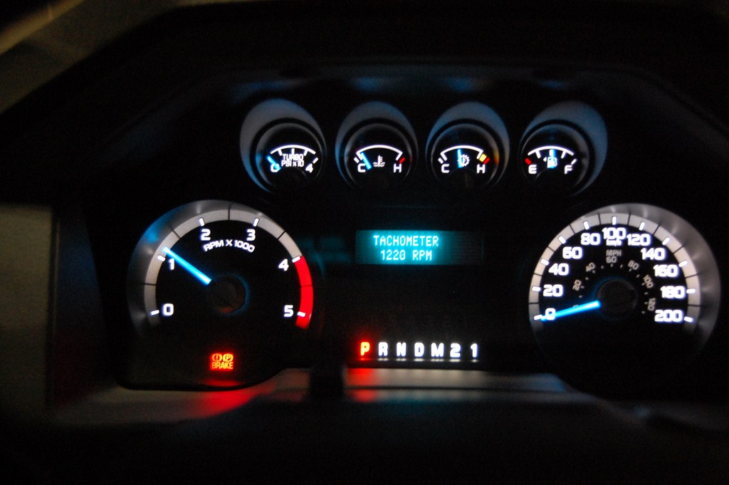
What is the actual RPM at high idle? Put the gauge cluster into engineering test mode. (Reset or Down arrow when cranking, release when the 4x2 icon appears or when the Ford advertisement is done.)
With my specific resistor, it runs at 1220RPM.
Further Thoughts
I am considering installing some liquid tight / TECK conduit leading out from the rear of the cab, down the frame into a Red Dot NEMA watertight enclosure with GFCI outdoor electrical socket located near the hitch (opposite from the side with the 7 and 4 pin) so I can conveniently plug things in without having to throw an extension cord out a window. I have installed 120V fluorescent lights inside a enclosed cargo trailer (those little 12V puck lights suck in terms of illumination) so this would supply the line voltage power to run the lights when there's nowhere to plug it in.
Radio Equipment
I kept the radios from my Tundra so I could reinstall them in the new truck.
I will be moving a bit faster on this write-up and gloss over with less detail than the inverter install because I assume that if you are planning on installing radio equipment in your vehicle, you have some understanding of how to use the equipment you're installing. My installation will likely be different than yours, so this should only be used as a guideline since there are many variables involved in a good radio installation and it depends on the application, frequency band, antenna design, performance requirements and power handling.
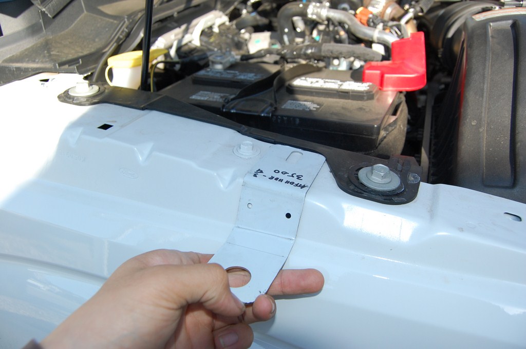
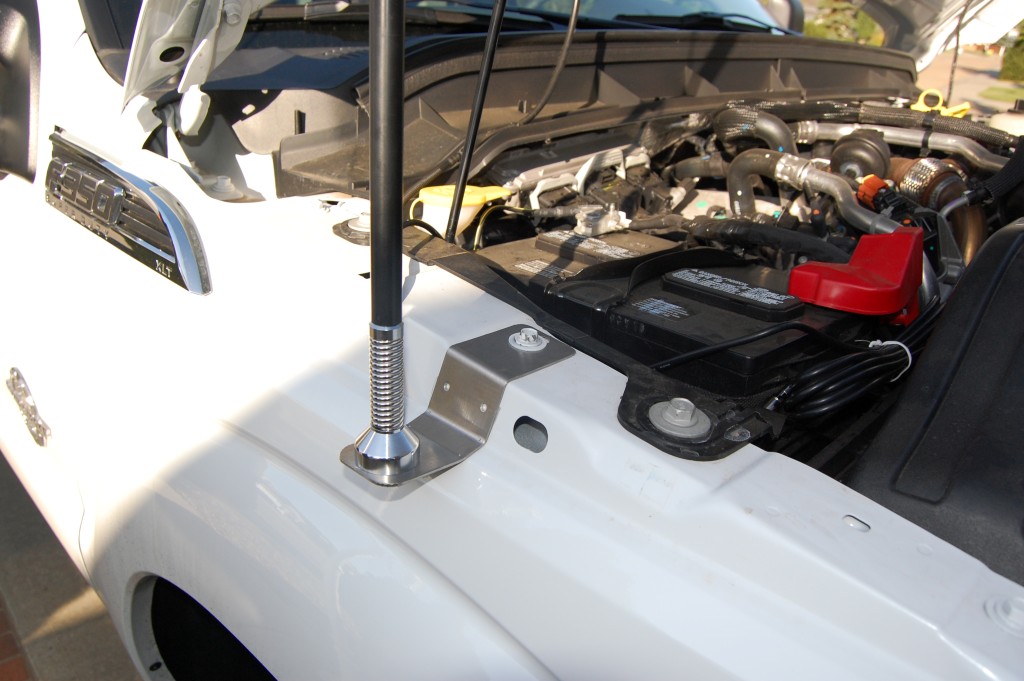
I decided on a fender antenna mounting because of the height issues associated with adding a 1.2 meter antenna to a truck that is already 6'10" tall. I have chosen a NMO (New Motorola) antenna system and stainless steel brackets are available for the 2011+ Super Duties and most radio shops have them. The left and right sides are different because of the slant of the fender piece. The brackets reuse the existing bolt. I added a layer of double sided mounting tape (3M VHB) under the bracket to prevent it from gouging into the vehicle sheet metal.
On this side I have a PCTEL MUF8455 850MHz 5dB gain elevated feed (no ground plane) antenna.
As indicated in the last section, I ran the antenna coaxial cable through the firewall in the same fashion that I ran the DC power cable for the inverter. Although through a different grommet.
I specifically did not want the Advanced Security Group package on my truck so I wouldn't have the door keypad. That also means I don't have the light sensor for the auto headlamps, so it becomes a convenient cable routing location.
Once the cover is off, the position of the hole should be apparent (during daylight hours or garage-light hours) under the dash.
Using normal wire fishing procedure, I pulled the first coax run. The coaxial cable I am using is a Larsen manufactured (sealed and weather tight) cable assembly with NMO on one end and FME on the other. This simplifies the installation process. I prefer the manufactured assemblies because a fender bracket NMO mount exposes the bottom of the connector to the outside, which will corrode the traditional solder-on NMO connectors. When used as originally intended (drilling a hole through the roof of your vehicle), the solder NMO connectors are not affected by this problem.
This line is connected to the mount that has my 850MHz antenna mounted on it, so I will use a FME to MiniUHF adapter to interface with the connector on the radio, a 12 watt Motorola GTX (800MHz side of the bandsplit)

I ran my second coaxial cable for the CB radio. Same process as the first one. The run is from the driver's side fender mount, with a Larsen NMO 27 antenna installed.
FME to UHF (PL-259) adapter installed to interface with the CB radio, a Cobra 29 LTD.
The cable fishing process is repeated for the power and PA lines.
Radios are hooked up to RF and power as required. Shrinkwrap was unsuitable for this so I had to use electrical tape.
I soldered the other end of the power wire to the Aux-2 upfitter line, Green/Brown. The convenient thing about the upfitters is that they are controlled by the ignition switch and are enabled in Acc or On.
Upfitter switches labelled.
I mounted the radio brackets to the tray. It was empty and asking to be filled with something.
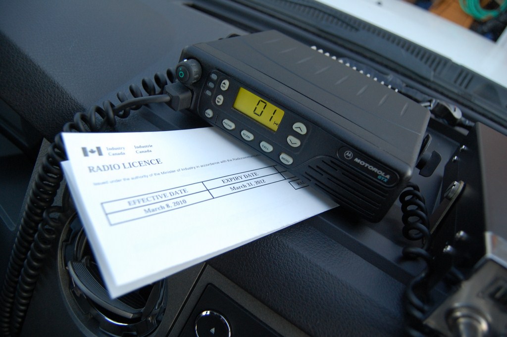
I can still kinda use the tray for paper. But I'll use it to hold my license (licence) papers.
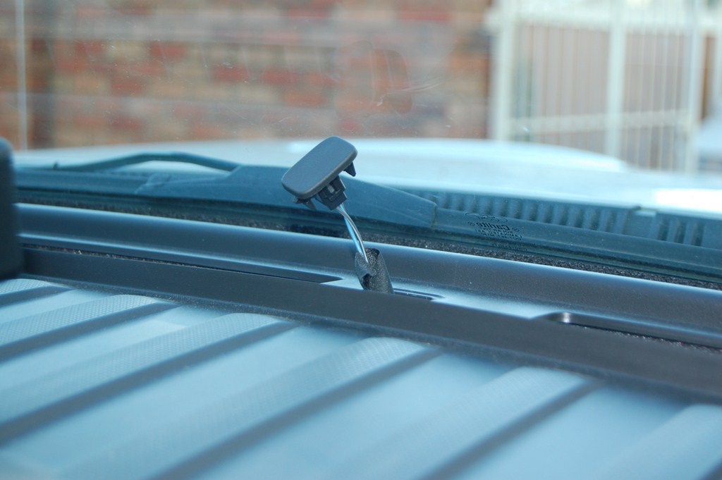
I mounted the microphone clips beside the cupholders. It's out of the way for the driver and any middle seat passengers. The Motorola microphones use the clip detection to switch between digital coded squelch (when it is in the clip) to carrier squelch (when it is removed from the clip) so you don't step on anyone else sharing the same frequency but on a different DCS code.
Tuning
I will quickly go over the tuning process for a CB antenna. Use the built in SWR function on the radio if it has one, or attach a forward/reflected/power meter inline to the radio.
Put the radio meter setting, or the separate meter into 'CAL' or Forward Power mode. Key down and adjust the 'SWR CAL' **** until the meter needle reaches full scale. Flip the meter mode to 'SWR' or Reflected power and read the scale. Make a mental note of this number. If your reading is higher than the middle of the scale or 3, stop and check the install. Flip the channel on the CB radio to 40 and repeat the process - CAL, adjust to full scale, SWR and read the number.
If the number (SWR) you read on Channel 40 is higher than on Channel 1 - which it should be if this is a brand new antenna - then remove the whip and cut tiny sections (1/8" or about 4mm at a time). Reinstall, and repeat the process. Stop cutting when the reading on Channel 40 is the exact same as Channel 1. Now go to Channel 20, the meter needle should not move.
I have always managed to get 1:1 matching at CH20 with CB on NMO antenna systems. It's tougher with the threaded peg style since the feed point is exposed and worst with the magnetic mount antenna systems which don't couple to ground properly.
If your antenna has a tuning screw, don't cut it, use the tuning screw.
If your numbers are consistently high, if it's swinging close the middle of the scale there is something wrong with the install. Check grounding, check that the coaxial cable has not been cut, and if you crimped your own ends, check that there are no stray strands of braid that have ended up on the center conductor.
Further Thoughts
I did not install the BCT15 radio scanner this time since I have a BC346XT handheld now.
If the radios flap around a bit too much and hit the tray and make noise, insert some high density foam (like from a pick-n-pluck equipment case) in between to reduce the movement.
I have not had engine noise issues mentioned in other threads.
I use the licensed Motorola radios (with the handheld pictured above) for situations where I need reliable communication. I hand out the portable units to people I want to talk to.
I use the CB to listen to whatever is on the band, and every so often there's useful info, otherwise it's just people illegally running too much power and complaining about the political state of the USA. It's what happens when a radio band goes license-free, it turns into a mess. But it's to talk to other people, let truckers know that their tire tread just came flying off their 53' trailer and I swerved just in time, etc.
Headache Rack and Rails
This is a work in progress and I am currently designing the project.
I fabricated a rack for my Tundra as well and it stayed with the truck when I traded for the F-350, since I built it specifically for that truck and it wouldn't look good on anything else.
I'm thinking of a similar design, 1.5" square tubing, angle iron and expanded metal. The movable piece will be slightly different than last time.
I will update this post and/or post a reply when I work it out.
Any questions? (And for goodness sake, don't quote the entire post when making a reply!)
And now that you know, don't be breaking into my truck. We all know how easy the handles come off...
This post will be updated accordingly as relevant (provided that edit functions do not expire on these forums).
As noted in the title of this thread, the usual items that I add to my trucks are:
- Power inverter
- Radio equipment
- Headache rack
2500W Sine Wave Power Inverter
Introduction and Rationale
Most people today are familiar with the applications of a solid state DC to AC power inverter, being to operate electronic or electrical devices designed for line voltage, normally 120VAC 60Hz.
Under normal circumstances, I use a power inverter to charge or operate computers, test equipment, and soldering irons. During power outage situations, I have operated network infrastructure equipment (telephone system, core network switch and routing devices) at a medium sized office off a 1kW modified square wave inverter. However, equipment does not run efficiently on modified square wave, hence the selection of a sine wave model.
I would like to clarify that my usage of a power inverter is not intended to replace the functions of a traditional moving field, engine driven electrical generator. It is intended as a convenience power source. The inefficiencies of an inverter installed as part of a vehicle's electrical system are far too great to consider this as a stationary power source when compared to a dedicated engine generator. Consider the massive vehicle engine driving a small belt driven alternator (auxiliary load) rectifying AC to DC, and then converted from DC to AC.
I own a small 15kW, split phase 1800RPM towable diesel generator set, but of course it depends on me actually having it with me since it is unlikely that I will just pull one around all the time 'just in case' for various reasons including but not limited to vehicle maneuverability, reduced vehicle fuel efficiency, and increased risk of theft. The inverter will be installed on the truck and is conveniently available.
Implementation
I ordered a SunForce 2500W Pure Sine Wave Inverter. In this application, the 2500W rating has been selected for its high surge capacity, and its price point in relation to a similar 1000W sine wave model inverter. I do not expect to be running close to maximum rated power on a long term basis.
In the past, I have always specified Xantrex brand power inverters and they have been of excellent build quality and operational stability. They are sold at a higher price point and are commonly used in RV applications. A comparable product would be a ProSine 1800, which runs from $800 to $1000 CAD. The SunForce I am using for this project cost $400 CAD. Throughout long-term use I will evaluate the differences, if any, between the brand name product and the lower cost product.
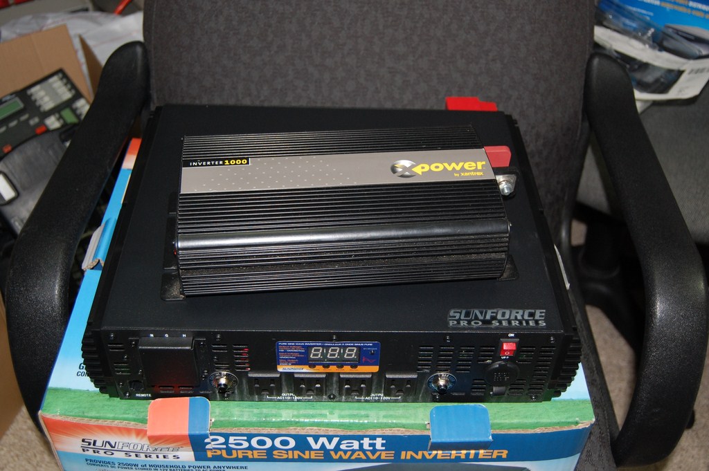
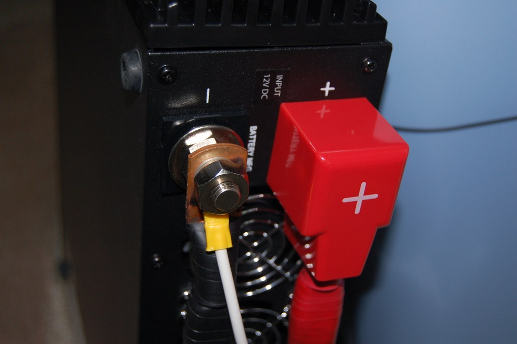
SunForce PSW 2500W compared to Xantrex MSW 1000W
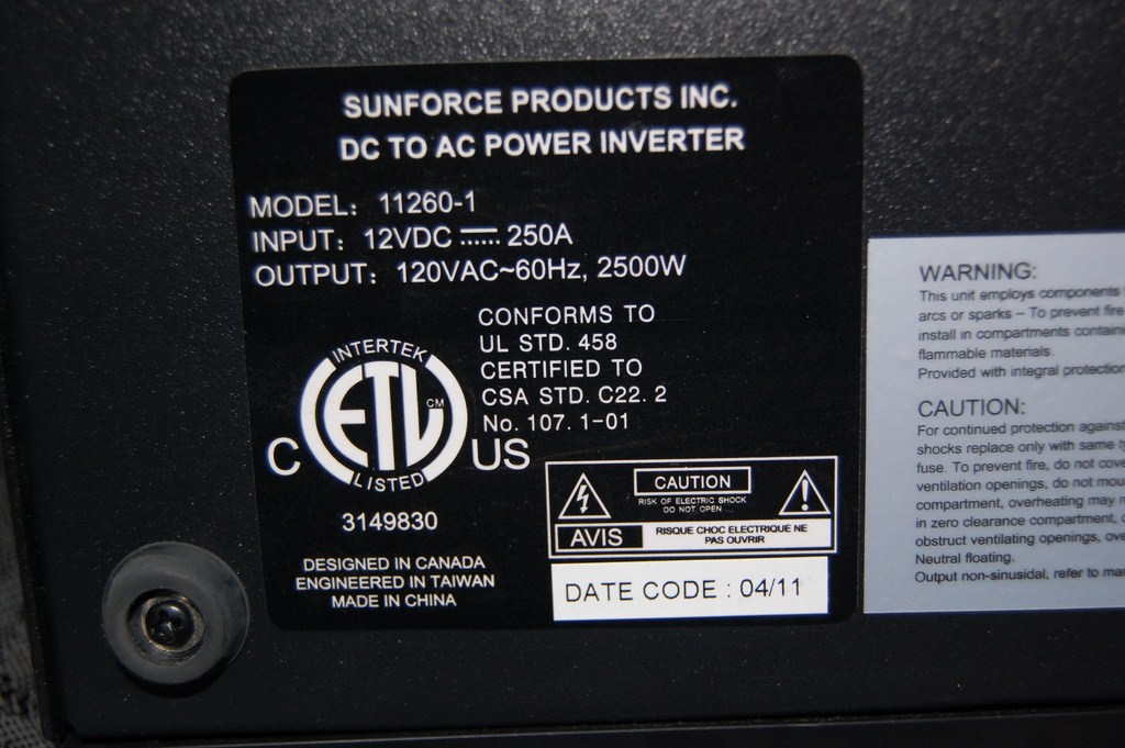
The dataplate rates a maximum current draw of 250 amps on the DC side.
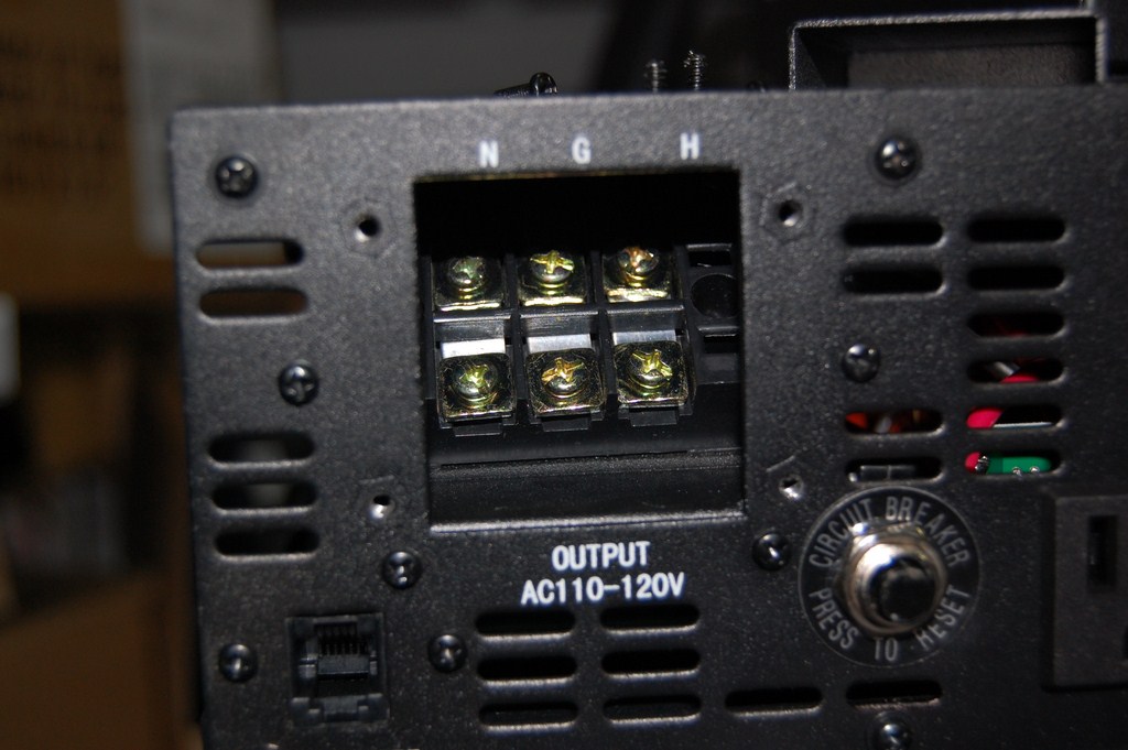
This model offers a terminal block for hard wiring devices.
Just to get an idea of internal build quality, I removed the side panels to observe the components.
There are 4 banks of semiconductors attached to large heatsinks. (The other 3 are behind this one in the picture)
A power inverter can be seen as a big amplifier running at higher voltages and tuned to work only at one frequency.
On the right, the DC terminal posts are seen. Note the use of parallel runs of 10AWG for easier wire routing and flexibility within the limited space within the product.
This inverter will have to be hard wired to the battery (most should if they're anything more than 400W). I considered using a high current DC-rated contactor with 12VDC coil winding as a positive disconnect device, however sourcing one was difficult and such a device would have been prohibitively expensive. I evaluated the parasitic current draw of the inverter in its 'off' state. This was evaluated without the use of the remote control receiver which is included with the product. I placed my meter in series with a regulated 13.8VDC 10A power supply (radio desktop power supply) for this test.
I decided that 200 microamps was negligible and would not discharge the battery, given the other stuff in the truck that operates on battery, and the transmission that likes to make meeping noises when the truck is shut off.
Now a note on cable sizing and ampacity. I selected 4AWG welding cable for this project due to availability, practicality, and cost. The ampacity of a cable is based partly on the wire insulation's ability to withstand heat and welding cable has thermoset sheathing with high temperature ratings. I've also used welding cable in its intended application running 170+ amps DC constant current with a jet rod without having the cable burst into flames. Therefore, I believe it is suitable for this task.
Furthermore, inverters are not dumb loads, they have inherent protection systems and monitor voltages and if too much energy is being dissipated as heat over the cable, there will be a voltage drop across the cable and it will be seen at the load end (inverter) end as a low voltage condition. The inverter will error out and shut off based on that.
Overkill is always a good thing, and you may instead choose to use 2/0 AWG wire or several parallel runs of a lower gauge. I would not argue with that practice.
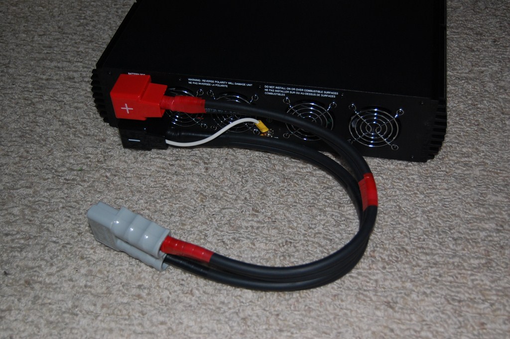
In place of a disconnect contactor, a high current 2-pole connector was used. It is important to note that connectors are generally not designed for current breaking so it should only be connected or disconnected with no load. I did not want to be attaching the cables to equipment (battery or inverter) live with a wrench, lest I slip and drop it across the terminals.
I soldered together a pigtail cable. The soldering was done with a blowtorch. This once again highlights the high temperature rating of thermoset insulation versus thermoplastic insulation which would rapidly burn off when exposed to a blowtorch flame. The connector lugs can also be crimped with a suitable crimping tool.
One end was terminated with the connector pin, the other terminated with a copper lug. A 12AWG line was used to tie the chassis ground (also ground pin on the AC side) to the negative terminal, being vehicle ground.
The connector I used was a clone of the Anderson PowerPole and is assembled (push until clicks) exactly like the brand name product. There are many variants of this. These are hermaphroditic connectors so the side doesn't matter.
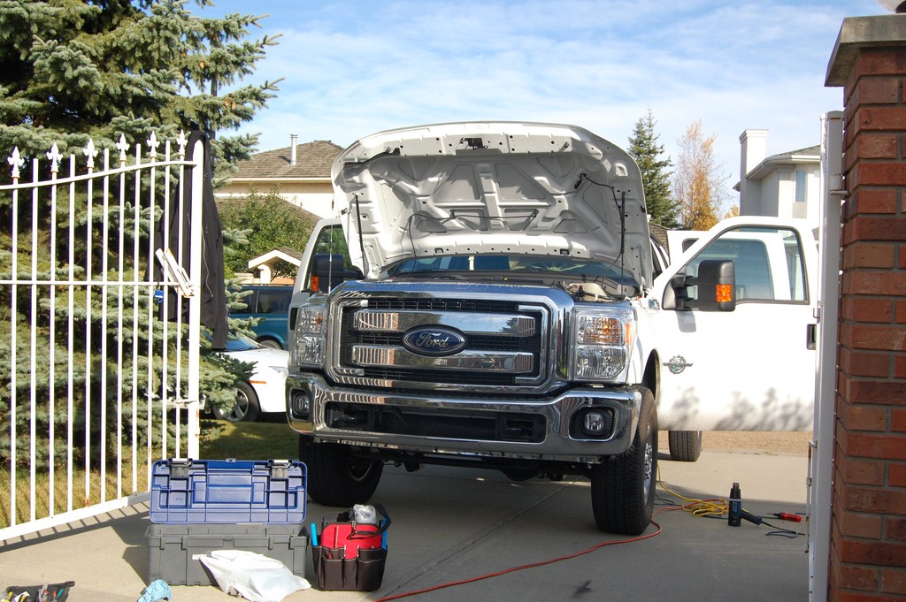
Now onto the vehicle side of the project... the rest of the steps will be in an order that is easier for explanation purposes, but is not necessarily the actual order I did them in. Therefore some of the pictures will go between daytime and night time and it may seem weird.
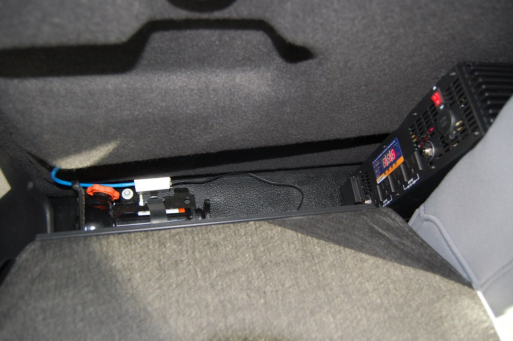
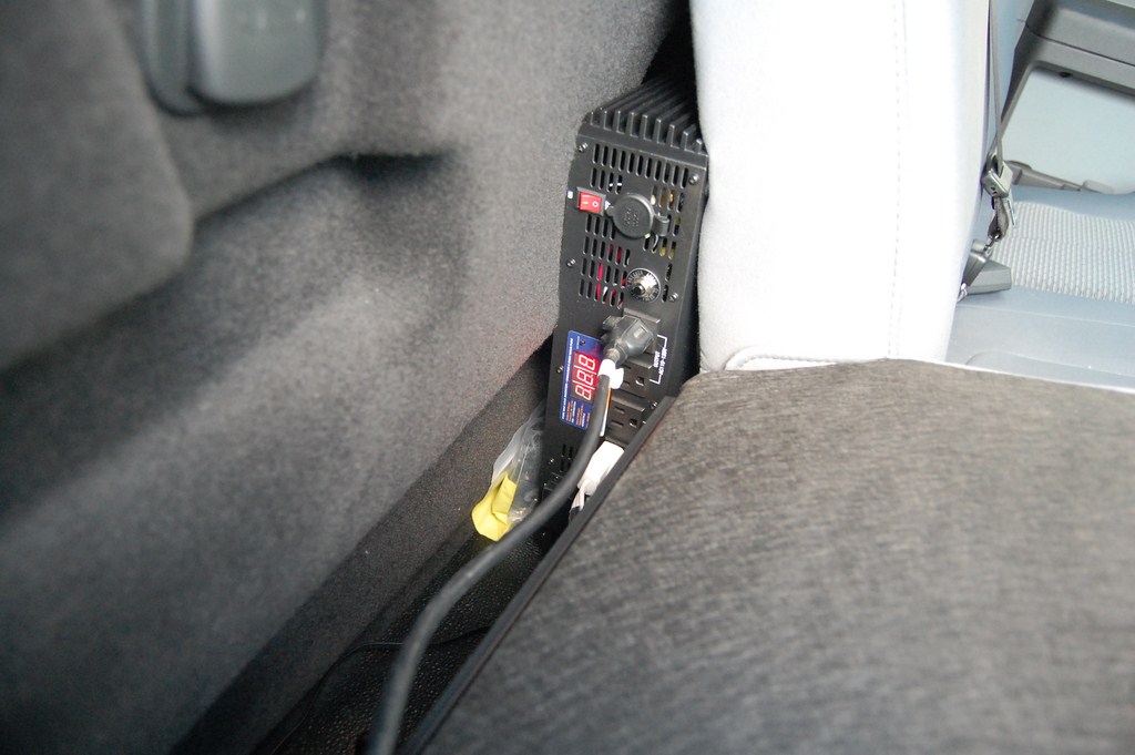
I decided to place the inverter behind the back seat since there was no other feasible location for the device. There is insufficient space under seats for this due to the floor air vents. If you don't have the storage tray under the rear seats it might be able to go there but passengers may be prone to kicking it.
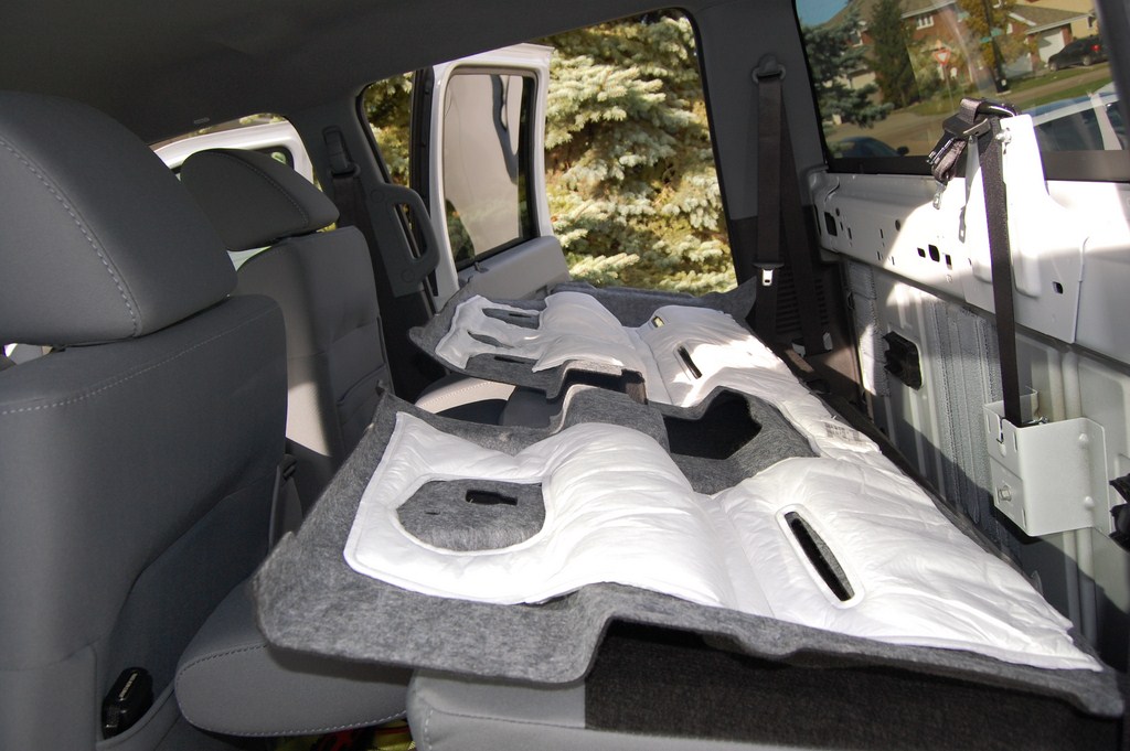
First step was to take out the "rat fur" (which is officially named the 'Ebony Ford NVH Enhanced Cab Back Panel W/Center Restraint - XLT & Above') and the C-pillar covers to make it easier to work in the area. The middle seat belt is unfastened with a thin object, like a finishing/picture hanging nail or a precision screwdriver.
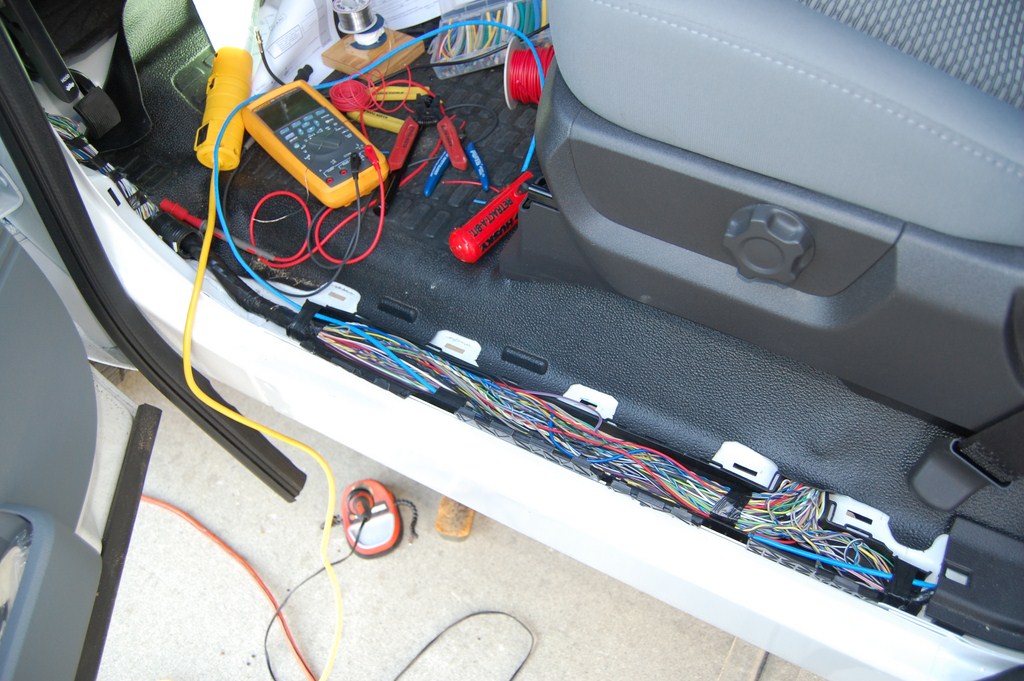
The kick panels come off by pulling on them. Like most everything in vehicles these days, it's snap fit. This reveals a sort-of cable tray which is already quite crowded. I chose the driver's side because the passenger side of the vehicle is totally packed with wiring, since the PCM is located halfway in the middle of the firewall on that side.
I ran the control wiring first. More on the control side later.
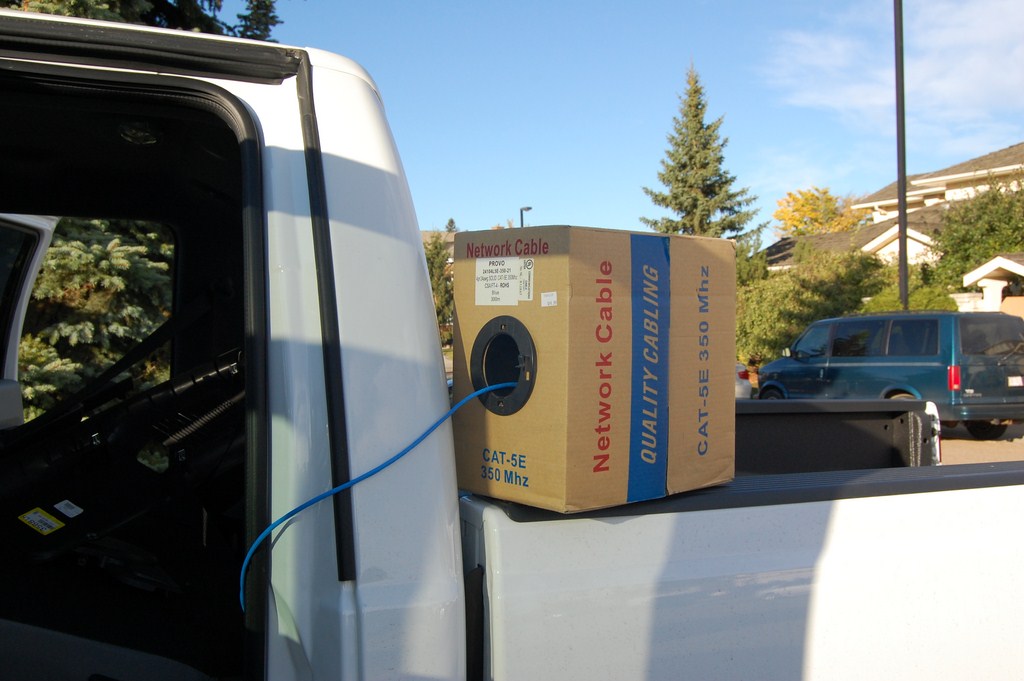
I used cat5e, because I'm a telecom guy and I just have too much of this stuff. Possible alternatives on the control side are Low Voltage Thermostat (LVT) cable, lamp cord, speaker wire, or individual wires twisted together.
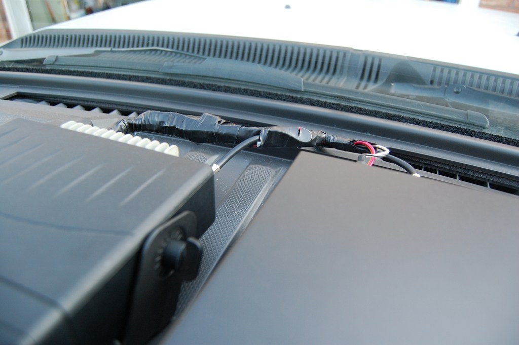
Control line run ends at under the dashboard.
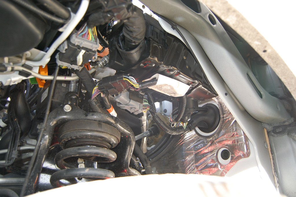
I pulled off the wheel well liner to get access to the firewall grommet. The crowded engine bay makes it very difficult to get to it from the top.
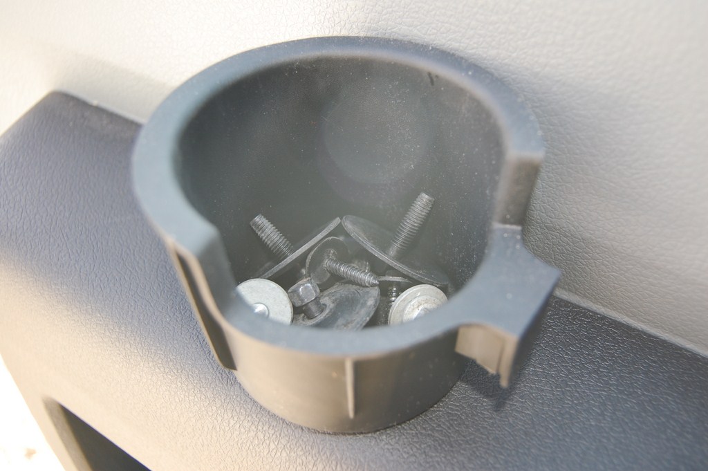
The removable cupholder inserts make convenient parts cups.
I ran the welding cable in the cable trough. If you chose to use 2/0 cable, it will probably not fit there and you will have to run the cable under the floor, or route it outside of the cab and run it inside the C-channel frame.
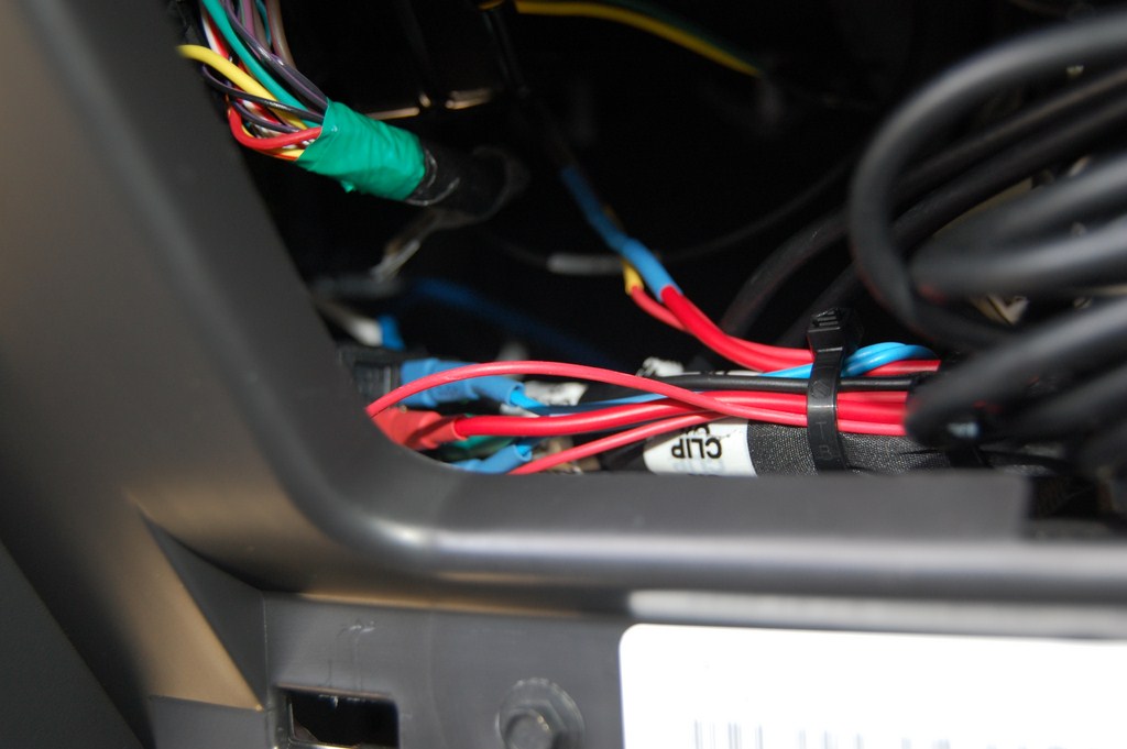
Poke it out through the grommet. Take care to not destroy the existing wiring harness that runs through it, because there are some duplicate wiring colours in there so it's going to be worse than trying to splice severed 50-pair phone line and wondering where the wire binder ribbon wrap went.
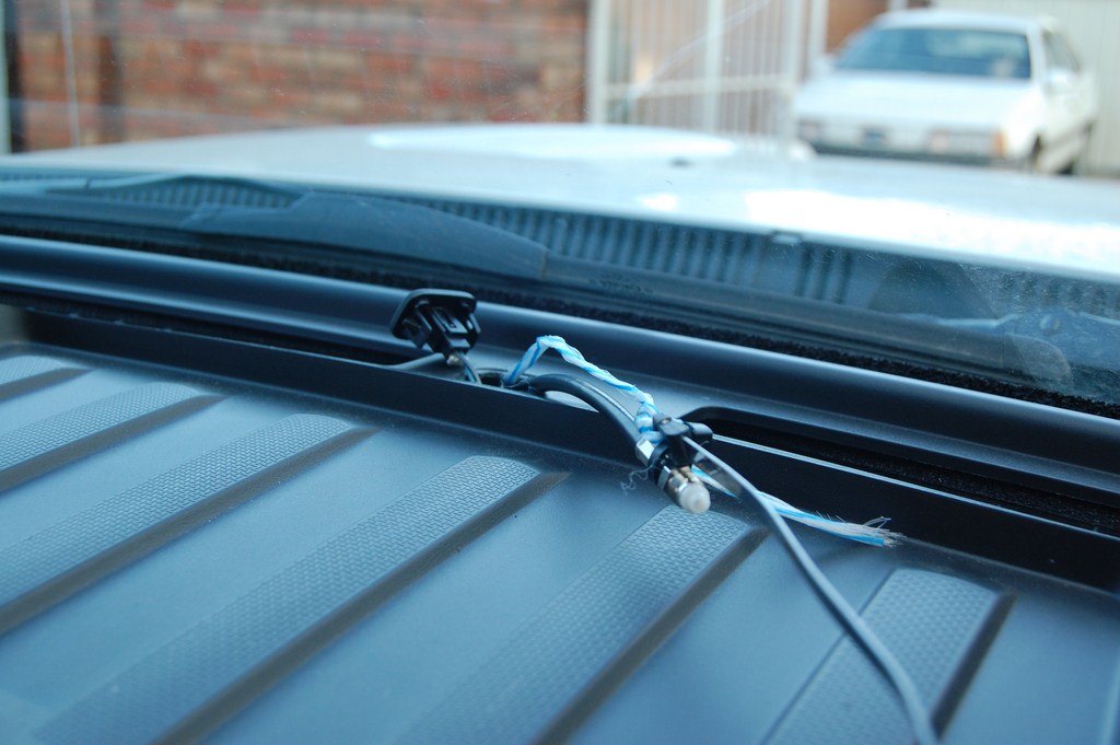
Now is a good time to run any other wires for other projects. I ran 2 coax runs for the radio antennas, documented later on.
Terminate the ends with the appropriate connectors. I soldered these ends as well with the propane blowtorch. As mentioned earlier, they can be crimped with the appropriate crimping tool as well.
Waiting for all the flux in the solder to burn up.
After this picture was taken the connector was wirebrushed clean to remove all the flux and other contaminants. Flux is a good insulator so make sure all the contacts are clean.
Replace cab back panel and C-pillar covers. At this point I assembled the DC side connector. Don't plug anything in yet!
The cable routes nicely out of the gap in the C-pillar cover. And I can still fit my first aid kit in that corner.
Terminate the engine bay side of the cable as appropriate (in this case, copper lugs). Ensure that the other end of the cable inside is NOT touching anything conductive. Check continuity between both cable runs and make absolutely sure that you have infinity ohms of resistance. Attach to the battery. Or hold on a second, a few more notes on best practices:
Ford recommends that on diesel engined vehicles with dual parallel batteries, you use the primary battery on the passenger side for electrical loads such as jump starting another vehicle. I have connected it to the secondary battery on the passenger side. The primary battery is hard to attach to due to the amount of other connections attached to it from factory installed electrical systems. Furthermore it results in a longer cable run and you have to take the long way around to avoid the engine components.
Standard electrical procedure specifies that a current interrupting device (circuit breaker, fuse) should be installed as close as possible to the power source to protect the wiring. Such a device will require some searching since you won't find it at a auto or hardware store and wholesale electrical distributors won't have high current DC rated circuit breakers. A store specializing in solar power systems would be your best bet. Perhaps a vehicle audio/entertainment systems installer may have such a thing kicking around. Marine supply shops may also have something similar, but we don't have those around here. I'm going to have to trust my own work.
Conversely, it is not normal practice to put breakers on huge telecom 48V battery banks which have more than 10 times the current capacity as your vehicle electrical system. (Electrical tape your wrenches!)
Also note that the factory parallel cable run between the batteries is not fused either.
Past that topic of potential internal controversy, check the polarity and voltage the other end and hook up the inverter.
If all goes well, the inverter turns on and the AC side will be outputting the correct voltage at a frequency reasonably close to specification.
This is enough work for basic inverter operation, but I continued on to add a control line to an upfitter switch and wire up Battery Charge Protect (BCP) and Stationary Elevated Idle Control (SEIC) functions.
At this point, reassemble the kick panels and the wheel well if that was removed.
Upfitter Switch Control
Per Ford bulletin Q-180-A, a resistor value of 20,000 ohms results in a high idle of 1200RPM. While BCP functions do not depend on a specific resistor value, it does require A resistor in the circuit. In addition, I plan on wiring SEIC enable to another upfitter switch.
I added wire leads to and shrinkwrapped a 1/2 watt 20k ohm resistor since they tend to be fragile on their own.
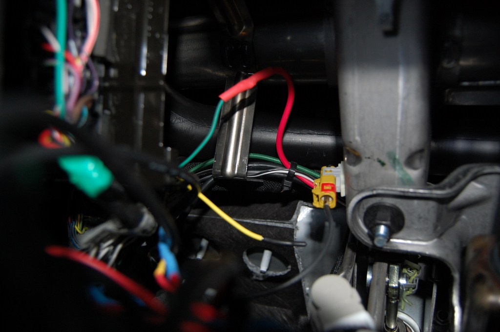
One side of the resistor goes to an accurately regulated 5 volt reference line from the PCM, White/Brown, the other to the PCM reference reading line, Green. The resistor that you add completes the voltage divider circuit, and the PCM reads the voltage drop across the resistor with a analog digital converter (ADC) to determine SEIC RPM.
Here I am verifying that I have indeed found the 5V reference line.
Solder, shrinkwrap, label. I'm not going to mention the alternate methods of connecting wires.
SEIC is easiest so I'll do that first. I selected AUX-3 for that purpose. The line for AUX-3, Violet/Green (on the harness behind the knee panel), supplies battery voltage to the PTO-REQ1 line, Yellow/Green.
Let's go back to the inverter. This inverter was supplied with a RF remote control module that plugged into the front panel of the inverter with a 6P6C modular jack. In the phone world it's a RJ-25. Upon disassembly and inspection of the remote control receiver module, the module simply closes a contact between the first pair tip and ring (Also known as... middle of the connector, 6-position jack: pins 3 and 4, Standard colour code: White/Blue and Blue/White, Old colour code: Green and Red). Remember that this is only the case with my inverter and may not apply to other models. You may have to hack the case and splice into the power switch wires.
By jumpering over those 2 wires, the inverter turns on. (Note front panel switch is in the off position.)
I used a surface mount jack aka "biscuit jack". Yeah, phone guy. Actually I can't think of anything better to use in this situation.
The control circuit is low current, but quantitatively, what does that mean?
It means 400 milliamps. Yes, the phone line and network cable will handle it.
Dig out the Cat5e line that was pulled earlier. I twinned the lines and used a pair for each side. This leaves 2 pairs free for future applications.
Close it up.
The upfitter switches control relays to supply 12VDC. Except I need dry contacts in this application. So, we will use another relay. I happen to have several boxes of new-old-stock Ford relays. (I actually use them on installations to wire up 70V overhead speaker paging systems onto phone systems and mute background music when the amplifier doesn't have a precedence feature. Pretty versatile.)
Ok, so the relay doesn't have to be Ford branded or Made in Canada or even have a normally closed contact or any high current rating, but it should have a 12VDC coil and a normally open contact.
Add wires to the relay. Or use a relay socket, if you have one kicking around.
Find the other end of the Cat5e (or whatever cable was used). These 2 wires should go between the common and the normally open contact on the relay.
The desired upfitter switch (I selected Aux-4, Brown on the harness behind the knee panel) should be connected to one side of the relay coil, the other side of the relay coil is grounded. I wanted BCP to be enabled whenever the inverter was turned on via upfitter switch (which will only apply when the vehicle is parked with parking brake applied) so I also wired Aux-4 to the BCP-SW wire, Violet/Brown.
At this point, the inverter should be turning on when Aux-4 is turned on with the key ignition switch in Acc or On. If the engine is running and the vehicle is parked, you will hear the engine RPMs change a bit as BCP is enabled.
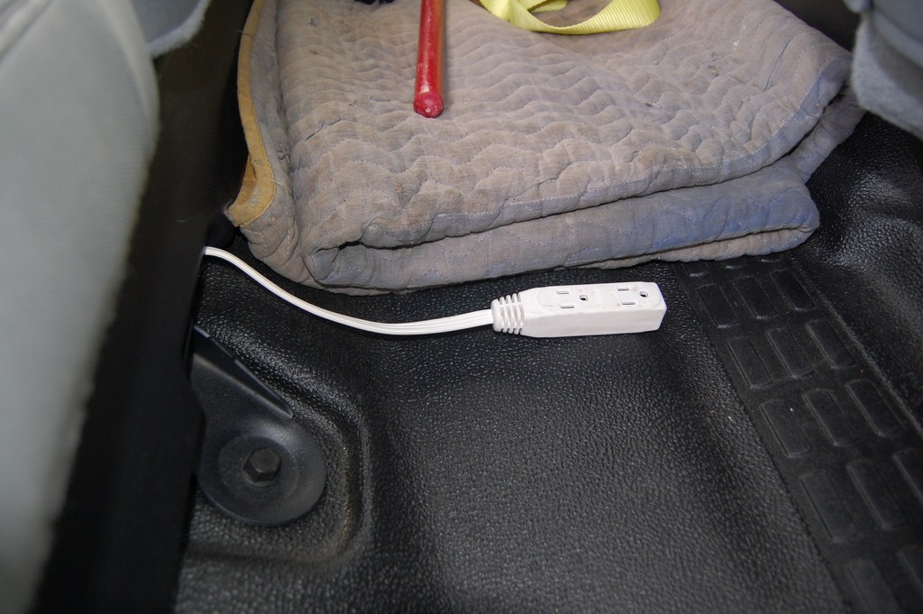
I also ran a light duty extension cord in the space between the two under-seat storage trays for convenient access by passengers. It tucks in to the space between the 60/40 seats when not in use.
Testing
I tested the inverter by running a small telephone switch off it, a little Option 11c. It only pulls about 350 watts, especially with only 1 phone powered off it, so it's not much of a load test as it is a test of clean power. Power supplies hum like mad when they are running off noisy square wave power. They are quieter when running off this inverter. The best part is that the inverter never really runs its fans since most loads are not stressing the unit at all.
Should have put the Hall effect current clamp meter on the DC cables to see what the DC current draw was. I'll have to try that sometime.
What is the actual RPM at high idle? Put the gauge cluster into engineering test mode. (Reset or Down arrow when cranking, release when the 4x2 icon appears or when the Ford advertisement is done.)
With my specific resistor, it runs at 1220RPM.
Further Thoughts
I am considering installing some liquid tight / TECK conduit leading out from the rear of the cab, down the frame into a Red Dot NEMA watertight enclosure with GFCI outdoor electrical socket located near the hitch (opposite from the side with the 7 and 4 pin) so I can conveniently plug things in without having to throw an extension cord out a window. I have installed 120V fluorescent lights inside a enclosed cargo trailer (those little 12V puck lights suck in terms of illumination) so this would supply the line voltage power to run the lights when there's nowhere to plug it in.
Radio Equipment
I kept the radios from my Tundra so I could reinstall them in the new truck.
I will be moving a bit faster on this write-up and gloss over with less detail than the inverter install because I assume that if you are planning on installing radio equipment in your vehicle, you have some understanding of how to use the equipment you're installing. My installation will likely be different than yours, so this should only be used as a guideline since there are many variables involved in a good radio installation and it depends on the application, frequency band, antenna design, performance requirements and power handling.
I decided on a fender antenna mounting because of the height issues associated with adding a 1.2 meter antenna to a truck that is already 6'10" tall. I have chosen a NMO (New Motorola) antenna system and stainless steel brackets are available for the 2011+ Super Duties and most radio shops have them. The left and right sides are different because of the slant of the fender piece. The brackets reuse the existing bolt. I added a layer of double sided mounting tape (3M VHB) under the bracket to prevent it from gouging into the vehicle sheet metal.
On this side I have a PCTEL MUF8455 850MHz 5dB gain elevated feed (no ground plane) antenna.
As indicated in the last section, I ran the antenna coaxial cable through the firewall in the same fashion that I ran the DC power cable for the inverter. Although through a different grommet.
I specifically did not want the Advanced Security Group package on my truck so I wouldn't have the door keypad. That also means I don't have the light sensor for the auto headlamps, so it becomes a convenient cable routing location.
Once the cover is off, the position of the hole should be apparent (during daylight hours or garage-light hours) under the dash.
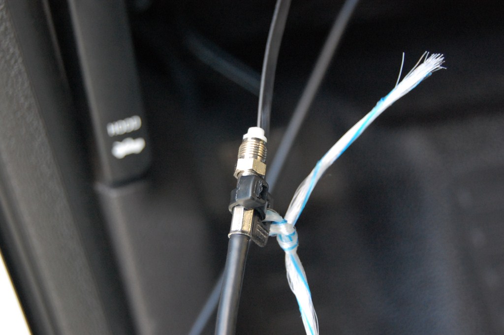
Using normal wire fishing procedure, I pulled the first coax run. The coaxial cable I am using is a Larsen manufactured (sealed and weather tight) cable assembly with NMO on one end and FME on the other. This simplifies the installation process. I prefer the manufactured assemblies because a fender bracket NMO mount exposes the bottom of the connector to the outside, which will corrode the traditional solder-on NMO connectors. When used as originally intended (drilling a hole through the roof of your vehicle), the solder NMO connectors are not affected by this problem.
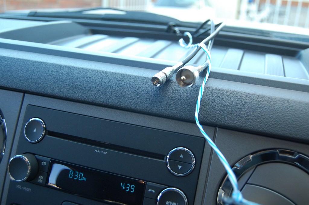
This line is connected to the mount that has my 850MHz antenna mounted on it, so I will use a FME to MiniUHF adapter to interface with the connector on the radio, a 12 watt Motorola GTX (800MHz side of the bandsplit)
I ran my second coaxial cable for the CB radio. Same process as the first one. The run is from the driver's side fender mount, with a Larsen NMO 27 antenna installed.
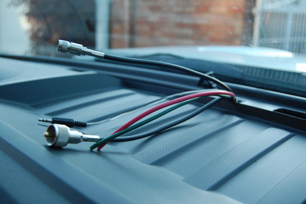
FME to UHF (PL-259) adapter installed to interface with the CB radio, a Cobra 29 LTD.
The cable fishing process is repeated for the power and PA lines.
Radios are hooked up to RF and power as required. Shrinkwrap was unsuitable for this so I had to use electrical tape.
I soldered the other end of the power wire to the Aux-2 upfitter line, Green/Brown. The convenient thing about the upfitters is that they are controlled by the ignition switch and are enabled in Acc or On.
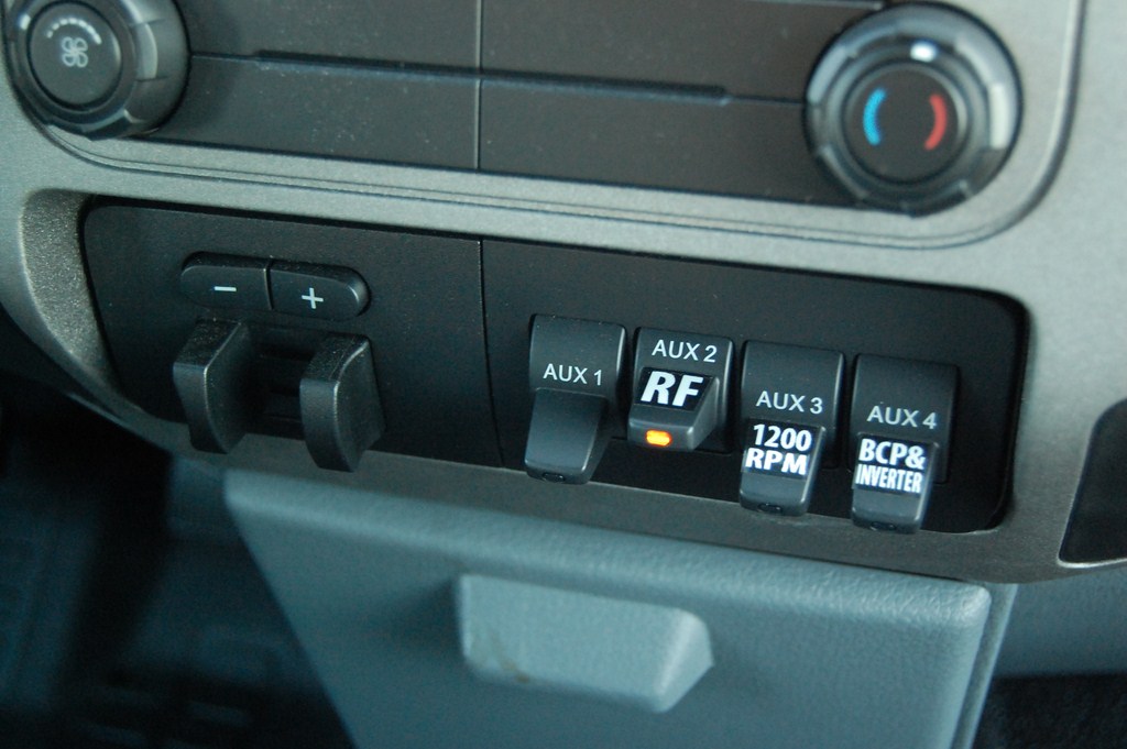
Upfitter switches labelled.
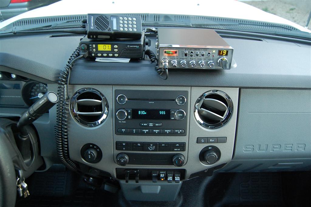
I mounted the radio brackets to the tray. It was empty and asking to be filled with something.
I can still kinda use the tray for paper. But I'll use it to hold my license (licence) papers.
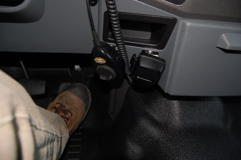
I mounted the microphone clips beside the cupholders. It's out of the way for the driver and any middle seat passengers. The Motorola microphones use the clip detection to switch between digital coded squelch (when it is in the clip) to carrier squelch (when it is removed from the clip) so you don't step on anyone else sharing the same frequency but on a different DCS code.
Tuning
I will quickly go over the tuning process for a CB antenna. Use the built in SWR function on the radio if it has one, or attach a forward/reflected/power meter inline to the radio.
Put the radio meter setting, or the separate meter into 'CAL' or Forward Power mode. Key down and adjust the 'SWR CAL' **** until the meter needle reaches full scale. Flip the meter mode to 'SWR' or Reflected power and read the scale. Make a mental note of this number. If your reading is higher than the middle of the scale or 3, stop and check the install. Flip the channel on the CB radio to 40 and repeat the process - CAL, adjust to full scale, SWR and read the number.
If the number (SWR) you read on Channel 40 is higher than on Channel 1 - which it should be if this is a brand new antenna - then remove the whip and cut tiny sections (1/8" or about 4mm at a time). Reinstall, and repeat the process. Stop cutting when the reading on Channel 40 is the exact same as Channel 1. Now go to Channel 20, the meter needle should not move.
I have always managed to get 1:1 matching at CH20 with CB on NMO antenna systems. It's tougher with the threaded peg style since the feed point is exposed and worst with the magnetic mount antenna systems which don't couple to ground properly.
If your antenna has a tuning screw, don't cut it, use the tuning screw.
If your numbers are consistently high, if it's swinging close the middle of the scale there is something wrong with the install. Check grounding, check that the coaxial cable has not been cut, and if you crimped your own ends, check that there are no stray strands of braid that have ended up on the center conductor.
Further Thoughts
I did not install the BCT15 radio scanner this time since I have a BC346XT handheld now.
If the radios flap around a bit too much and hit the tray and make noise, insert some high density foam (like from a pick-n-pluck equipment case) in between to reduce the movement.
I have not had engine noise issues mentioned in other threads.
I use the licensed Motorola radios (with the handheld pictured above) for situations where I need reliable communication. I hand out the portable units to people I want to talk to.
I use the CB to listen to whatever is on the band, and every so often there's useful info, otherwise it's just people illegally running too much power and complaining about the political state of the USA. It's what happens when a radio band goes license-free, it turns into a mess. But it's to talk to other people, let truckers know that their tire tread just came flying off their 53' trailer and I swerved just in time, etc.
Headache Rack and Rails
This is a work in progress and I am currently designing the project.
I fabricated a rack for my Tundra as well and it stayed with the truck when I traded for the F-350, since I built it specifically for that truck and it wouldn't look good on anything else.
I'm thinking of a similar design, 1.5" square tubing, angle iron and expanded metal. The movable piece will be slightly different than last time.
I will update this post and/or post a reply when I work it out.
Any questions?
(And for goodness sake, don't quote the entire post when making a reply!)And now that you know, don't be breaking into my truck. We all know how easy the handles come off...


#3
11-12-2011, 06:20 AM

Lead Driver
#4
11-12-2011, 07:57 AM
#5
11-12-2011, 09:25 AM
Postmaster
#7
11-12-2011, 01:54 PM
Cargo Master
Trending Topics
#8
11-12-2011, 03:22 PM
#9
11-13-2011, 07:23 PM
Junior User
Join Date: Mar 2011
Location: NW Wisconsin
Posts: 77
Likes: 0
Received 0 Likes
on
0 Posts
#10
11-19-2011, 09:07 PM
Posting Guru
Join Date: Jul 2006
Location: Fairfield, CA
Posts: 1,181
Likes: 0
Received 0 Likes
on
0 Posts
I read this fantastic thread about a week ago and had to come back and share this ridiculous ebay posting I found by chance.
10000W max 5000W pure sine wave power inverter 12VDC/110VAC 60Hz power converter | eBay
But it gets even better If you know anything about Grid-tie PV systems with this listing:
New 1200W grid tie inverter,28-52V DC/110V AC FUSE 60Hz wind turbine/solar panel | eBay
Enjoy!
10000W max 5000W pure sine wave power inverter 12VDC/110VAC 60Hz power converter | eBay
But it gets even better If you know anything about Grid-tie PV systems with this listing:
New 1200W grid tie inverter,28-52V DC/110V AC FUSE 60Hz wind turbine/solar panel | eBay
Enjoy!
#11
11-20-2011, 01:18 AM
Lmao Engrish at its best.
traditional grid tie inverter is the solar panel are connect in series, so if one solar panel did not work or bad efficiency, then the whole system will be effects, but power jack grid tie inverter, you can use every inverter in parallel, in this moment, each inverter has it's own MPPT, can make every solar panel got the max power.
#13
10-26-2014, 12:36 AM


Thread
Thread Starter
Forum
Replies
Last Post
Jesser02EX
1999 - 2003 7.3L Power Stroke Diesel
88
11-05-2021 08:38 PM
Wookie06
1999 to 2016 Super Duty
3
09-11-2012 02:01 PM

