
Beefy Trans Mods?
#1
 10-03-2011, 10:58 AM

 6.0 cooler. Must have a trans temp gauge.
#3
10-03-2011, 01:25 PM

E4OD Mega Monster Transmission Complete Rebuild Kit: 1989-95 You could go with something like this when rebuilding.
Plan B would be to just get a John Woods trans and have done with it.
Plan B would be to just get a John Woods trans and have done with it.
#4
10-03-2011, 01:37 PM
So the monster is an upgrade then? I am actually brand new to fords. Have always had a chevy 1500 so this is all new to me lol the whole diesel power thing :thumbsup:
I'll keep the rebuild in mind but I'll definitly look into the valve body. Where is the shifting solenoid. The trany is shifting hard and I've been told thats what the issue is.
thanks!
I'll keep the rebuild in mind but I'll definitly look into the valve body. Where is the shifting solenoid. The trany is shifting hard and I've been told thats what the issue is.
thanks!
#5
10-03-2011, 01:42 PM
The trans is computer controlled and hard shifts usually means that the computer has detected a problem (usually a sensor) and has increased the line pressure. This is usually accompanied with a flashing OD light.
Your best bet, I would think, is to get it scanned for trouble codes to pin-point the problem.
Your best bet, I would think, is to get it scanned for trouble codes to pin-point the problem.

#7
10-03-2011, 02:15 PM
Trending Topics
#9
10-03-2011, 02:43 PM
#12
10-03-2011, 03:10 PM
#13
10-03-2011, 03:29 PM
https://www.ford-trucks.com/forums/7...m-problem.html Scroll down this thread for a pinout, should be similar to yours.
The IDI diesel and the 7.3 PSD have the same bolt pattern so the E4OD from one will bolt to the other, however the flexplates are different.
The IDI diesel and the 7.3 PSD have the same bolt pattern so the E4OD from one will bolt to the other, however the flexplates are different.
#14
10-03-2011, 03:37 PM
thanks lazy! okay so maybe this is a question for you.. When I put a TBI 350 in my Jeep cj I just used the harness how it came out of the chevy and where the it use to get 12v ignition from the chevy I just rewired that from the jeep ignition and also gave it its normal 12v to the power block with all the relays etc.
Will I be able to do the same type of thing here so I have all the same for stuff. And just jump the 12v that use to go to the I of the starting solenoid to the ignition wire of the computer with a 12v relay for better power? Then once the computer is powered it will run the fuel pump and the motor etc.??
Also do you know if there is a list somewhere of what each pin does? For example this was what I used for the chevy.
A1- grn/wht- this wire is used to energize the fuel pump relay.
A2- not used
A3- not used
A4- gry- to EGR relay.(optional) This is a ground from the ECM to control the EGR relay.
A5- brn/wht- SES(service eng soon) light. This is a ground to turn on the light.
A6- pnk/blk- switched 12v from the ignition relay.
A7- not used
A8- orn- ALDL Serial data. This is your ALDL pin E data for your lap top.
A9- wht/blk- ALDL pin B diag mode. When jumpered to ground will set the ECM to ALDL diagnostic mode.
A10- brn- VSS speed sensor signal to the ECM (optional)
A11- ppl or blk- MAP sensor ground.
A12- blk/wht- System ground. Can be tied with D1. Goes to engine ground.
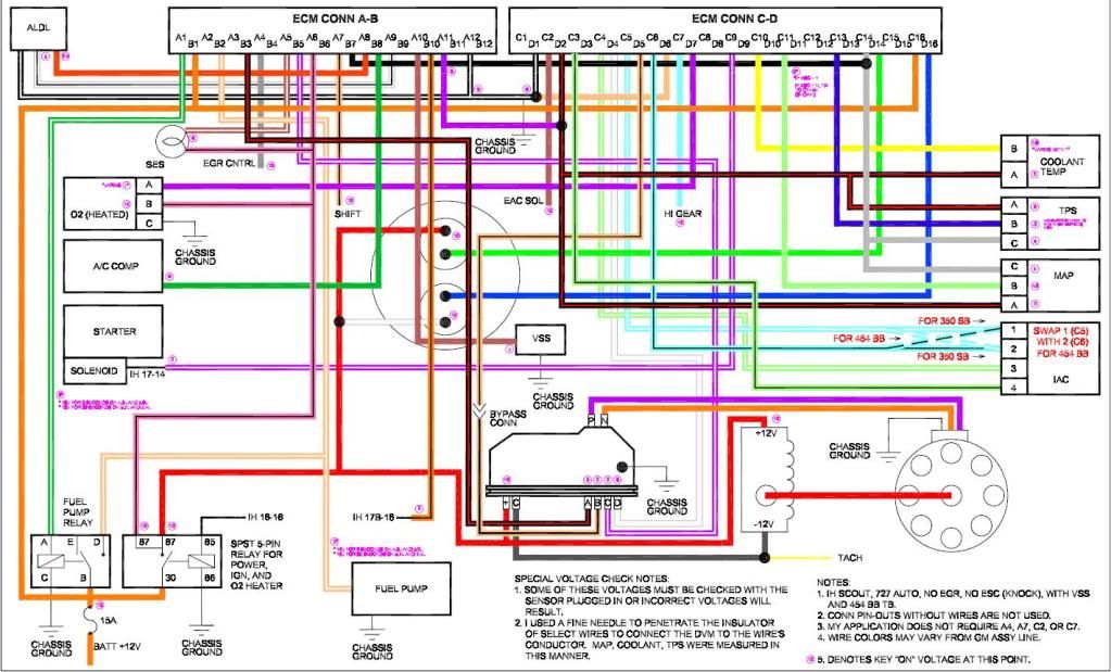
Just to clear the confusion on which pins are grounds I have taken a C3 ECM apart and labeled the pin locations on the plugs.
If you look you can see that D1 and D2 are solder connected and A11 and A12 are also connected.
So if either one of the two, example: D1 and A11 are grounded the other one will be. D2 and A12.
SEE PIC BELOW
B1- orn- 12v fused from battery. I use an inline fuse on this. It also ties into C16.
B2- tan/wht- Fuel pump signal from the relay. This one ties into several places, the fuel pump, the relay, and the ecm. When the relay is on it sends 12v thru this wire to turn on the fuel pump, at the same time it tells the ECM the fuel pump is on.
B3- blk/red- EST reference.
B4- not used
B5- ppl/wht- EST high reference
B6- not used
B7- blk- ESC signal This is the knock sensor signal to the ECM. The knock sensor circuit is optional. If not used, tie this wire to C14 the 5v reference. This will fool the system sometimes but you will need to program the chip to prevent the SES light from coming on.
B8- dk grn- AC signal. This tells the ECM that the AC is turned on. This can be used to set the idle speed higher when you turn the AC on. I use it to increase the idle when using the compressor for on board air. Same thing!! Just tie it to the wire going to the AC clutch.
B9- not used
B10-orn/blk- Park/Neutral sw. This is optional but I have hooked it into the park sw on the tranny. It tells the ECM when you are in Pk or N. It can be used to give a slight adjustment to idle speed when switching from park to drive and back.
B11- not used
B12- not used
C1- not used
C2- not used
C3- IAC- Idle air control
C4- IAC
C5- IAC
C6- IAC -The ECM controls the IAC motor. It adjust the amount of air that is bypassed around the butterflies to adjust the idle speed.
Note: (For the IAC pins C5 and C6 are reversed on the 454 vs the SBC so swap those 2 pins if using a 454 TB with the bolt on IAC.)
C7- not used
C8- not used
C9- ppl/wht- Starter crank signal. Goes to the small terminal of the starter. The stock scout wire is white that goes there. Tells the ECM you are trying to start the engine.
C10- yel- Temp sender signal
C11- lt grn- Map sensor signal
C12- (1228746 only) IAT/MAT sensor
C13- dk blu- TPS sensor signal
C14- gry- 5v reference signal to map and TPS.
C15- grn- inj B ground signal. Most systems do not use this. It was used on some of the bigger engines to share the load of the injector signal.
C16- orn- fused 12v tied to B1
D1- blk/wht- System ground, ties to A12 and engine.
D2- blk- Sensor ground. To eng block or head.
D3- not used
D4- wht- EST control
D5- tan/blk- EST bypass. This is the wire that has a plug near the distr that you disconnect to set your timing.
D6- Tan- O2 ground to engine.
D7- ppl- O2 sensor signal
D8- D13 not used
D14- lt grn- Injector B ground signal
D15- blu- optional injector A ground signal
D16- blu- Injector A ground signal
Thanks alot!
Devin
Will I be able to do the same type of thing here so I have all the same for stuff. And just jump the 12v that use to go to the I of the starting solenoid to the ignition wire of the computer with a 12v relay for better power? Then once the computer is powered it will run the fuel pump and the motor etc.??
Also do you know if there is a list somewhere of what each pin does? For example this was what I used for the chevy.
A1- grn/wht- this wire is used to energize the fuel pump relay.
A2- not used
A3- not used
A4- gry- to EGR relay.(optional) This is a ground from the ECM to control the EGR relay.
A5- brn/wht- SES(service eng soon) light. This is a ground to turn on the light.
A6- pnk/blk- switched 12v from the ignition relay.
A7- not used
A8- orn- ALDL Serial data. This is your ALDL pin E data for your lap top.
A9- wht/blk- ALDL pin B diag mode. When jumpered to ground will set the ECM to ALDL diagnostic mode.
A10- brn- VSS speed sensor signal to the ECM (optional)
A11- ppl or blk- MAP sensor ground.
A12- blk/wht- System ground. Can be tied with D1. Goes to engine ground.
Just to clear the confusion on which pins are grounds I have taken a C3 ECM apart and labeled the pin locations on the plugs.
If you look you can see that D1 and D2 are solder connected and A11 and A12 are also connected.
So if either one of the two, example: D1 and A11 are grounded the other one will be. D2 and A12.
SEE PIC BELOW
B1- orn- 12v fused from battery. I use an inline fuse on this. It also ties into C16.
B2- tan/wht- Fuel pump signal from the relay. This one ties into several places, the fuel pump, the relay, and the ecm. When the relay is on it sends 12v thru this wire to turn on the fuel pump, at the same time it tells the ECM the fuel pump is on.
B3- blk/red- EST reference.
B4- not used
B5- ppl/wht- EST high reference
B6- not used
B7- blk- ESC signal This is the knock sensor signal to the ECM. The knock sensor circuit is optional. If not used, tie this wire to C14 the 5v reference. This will fool the system sometimes but you will need to program the chip to prevent the SES light from coming on.
B8- dk grn- AC signal. This tells the ECM that the AC is turned on. This can be used to set the idle speed higher when you turn the AC on. I use it to increase the idle when using the compressor for on board air. Same thing!! Just tie it to the wire going to the AC clutch.
B9- not used
B10-orn/blk- Park/Neutral sw. This is optional but I have hooked it into the park sw on the tranny. It tells the ECM when you are in Pk or N. It can be used to give a slight adjustment to idle speed when switching from park to drive and back.
B11- not used
B12- not used
C1- not used
C2- not used
C3- IAC- Idle air control
C4- IAC
C5- IAC
C6- IAC -The ECM controls the IAC motor. It adjust the amount of air that is bypassed around the butterflies to adjust the idle speed.
Note: (For the IAC pins C5 and C6 are reversed on the 454 vs the SBC so swap those 2 pins if using a 454 TB with the bolt on IAC.)
C7- not used
C8- not used
C9- ppl/wht- Starter crank signal. Goes to the small terminal of the starter. The stock scout wire is white that goes there. Tells the ECM you are trying to start the engine.
C10- yel- Temp sender signal
C11- lt grn- Map sensor signal
C12- (1228746 only) IAT/MAT sensor
C13- dk blu- TPS sensor signal
C14- gry- 5v reference signal to map and TPS.
C15- grn- inj B ground signal. Most systems do not use this. It was used on some of the bigger engines to share the load of the injector signal.
C16- orn- fused 12v tied to B1
D1- blk/wht- System ground, ties to A12 and engine.
D2- blk- Sensor ground. To eng block or head.
D3- not used
D4- wht- EST control
D5- tan/blk- EST bypass. This is the wire that has a plug near the distr that you disconnect to set your timing.
D6- Tan- O2 ground to engine.
D7- ppl- O2 sensor signal
D8- D13 not used
D14- lt grn- Injector B ground signal
D15- blu- optional injector A ground signal
D16- blu- Injector A ground signal
Thanks alot!
Devin
#15
10-03-2011, 03:48 PM