
Where is the ammeter shunt located?
#16
 11-16-2010, 09:23 AM


As for them working the same, it is simply not true. An ammeter measures current flow and must somehow be in the circuit in a location where current flows across it. The voltmeter measures voltage and can be paralleled anywhere and the only current flowing across it will be due to the internal resistance of the meter.
#17
11-16-2010, 09:32 AM

As for them working the same, it is simply not true. An ammeter measures current flow and must somehow be in the circuit in a location where current flows across it. The voltmeter measures voltage and can be paralleled anywhere and the only current flowing across it will be due to the internal resistance of the meter.
#18
11-16-2010, 09:42 AM
I understand what you are saying, but look at my example. If you were to change the resistance of the shunt wire you will affect a change in the meter, meanwhile the voltage drop stays the same, at 12 volts.
Just because the ammeter is on a shunt does not mean that it is suddenly a glorified volt meter.
Ultimately it's not worth fighting over. There are pro's and con's to each, which is exactly why whenever I can afford to do my aftermarket gauges, one of them will be a voltmeter. Having both gives a complete picture, whereas having either one only gives part of the story and we can both argue the point until we're blue in the face and to what end? Seeing who can get bluer?
Your truck just came with an idiot light, to which case it is much easier, and much more practical to put in a voltmeter, so put in a voltmeter! It is hardly practical to install an ammeter aftermarket! For those of us who do have ammeters, however, it is important that we understand enough about the system so that they read correctly, and that is what the original poster intended. He knew that the way his accessories were connected was causing his meter to give him a false charge, which made it wholly useless and wanted to correct that. He knew the answer already, just wanted to verify it.
We're all here to help, not fight right?
For some reason I can't get the image of Bugs Bunny and Daffy Duck arguing over it's duck season or rabbit season out of my head.
#19
11-16-2010, 09:59 AM
Definitely understood - but I'm talking about the mechanics of what causes the needle to deflect, not the application. Is it a voltage across the gauge terminals, or a small current through them? I'm talking about the factory Ford gauge - not a theoretical ammeter. I am not convinced they are one in the same.
There are two ways to measure current: (1) use a voltmeter to measure the voltage drop and calculate the current using a known resistance, or (2) use an ammeter to measure the current in series with the circuit. My understanding was that although it's called an ammeter, it's actually done in method (1) specifically in the Ford setup. I guess the only way to be sure would be to actually test one, and to measure the impedance of the factory gauge. I don't have one, so I have not done this - this is just my understanding based on numerous threads in the Electrical forum and discussions in the past. A quick search will show you what I mean. If it's wrong, then I'm happy to understand how. I just haven't seen someone actually bench test one to show how it reacts, and I think that's really the only way to truly understand which way it works.
You're right that the voltmeter method requires a known resistance which can change as the harness ages, but the same is true for a shunt ammeter. The needle swing for a shunt ammeter is a function of the ratio of the resistance between the shunt and the winding resistance of the ammeter, because of current division. It's even shown in your analysis on paper.
Agreed 100% - but if my understanding is wrong, I want to understand how to fix it, and be convinced of why it's not correct, which at this point I'm not (but I'm always willing to learn). The factory Ford gauge could very well act as a true ammeter - that just isn't what I've been told, and it's theoretically possible for either method to work. At this point I have no data for or against the idea.
#20
11-16-2010, 10:19 AM
You can have a voltage with no current but you can't have a current with no voltage.
If you were to connect that meter directly to the terminals of a battery, current is going to flow across it based on whatever the internal resistance of the meter is. It will probably be so high that it will blast the meter to kingdom come. Assume though that the meter doesn't blow up. Now reverse the polarity of the battery and you will see the meter swing the other way. Now connect it to an AC source and it should either swap REALLY fast, or it will show a net 0 because the polarity of the voltage and thus the current flow direction changes, and changes so fast that the gauge can't respond. In all three cases the voltage number is the same.
The question then becomes, like you said, what deflects that needle? It's the magnetic field induced by the current in the circuit. So in reality, even your voltmeter is measuring current. It just happens to be measuring that current across some known internal resistance. In this manner I can see how it would seem that the factory ammeter appears to work the same. The physics behind the gauges work the same, it's just that the voltmeter has it's internal resistance and "calculates" voltage based off of current and known resistance. An ammeter shows current only, regardless of resistance or voltage in the line. The physical movement of the gauge, what causes them to work is the same. The difference is where they are connected in the circuit as to what information they give you. This is why the old analog multimeters were able to be a voltmeter or an ammeter, it just depends on what they are connected to, same gauge, however.
The reading from the ammeter is no less valid because it's on a shunt. That sort of thing is used all the time in electrical power distribution. You can see hundreds or even thousands of amps across a tiny little gauge not much bigger than what is in our trucks. But in a substation, you will also see a voltmeter!
So like you said, you could have a voltage regulator allowing 18 volts and the ammeter would be none the wiser. Likewise, however, you could have a voltmeter reading 13.5 volts and not be charging anything because there may not even be a battery present!
#21
11-16-2010, 12:44 PM
I have enjoyed reading this thread, made me think and challenged my electrical theory.
I guess I would have to say current is �more� correct then voltage as far as what cause the needle to deflect. But in my mind it is easier for me to understand the concept as� applied voltage dropping across the internal resistance of the meter is what causes the current to flow internally in the meter movement. All of the resistances in the circuit are fixed and thus in my mind, the changing voltage across the shunt ends up causing the amp meter needle to move�while this analogy might be technically flawed� my mind just likes it better.
I guess I think you are both correct�.
Anyway moving on to the G3 ALT �upgrade�� I still have not installed the 3G ALT I recently got at the junk yard as I am frustrated with loosing the amp meter. I really don�t need the extra amps, I just don�t like my current fire hazard 2G ALT, and it�s also the worst designed ALT I have ever seen.
So I have thought about making my own shunt but I don�t know the currently installed amp meter �Rm and Ifs��. Here a good link to what I am talking about�.
http://www2.ece.ohio-state.edu/~fior...onvalMeter.pdf
I do plan on doing some bench testing with a ford amp meter at some point down the road.
Another idea would be to just de-rate the 3G with a 60 circuit breaker and using the current wiring harness/shunt. The only risk I can see with this plan is popping the CB with a totally dead battery and thus forcing me to idle the engine, to limit ALT amp output, until the battery is charged enough to draw less than say... 20amps.
Any thoughts�
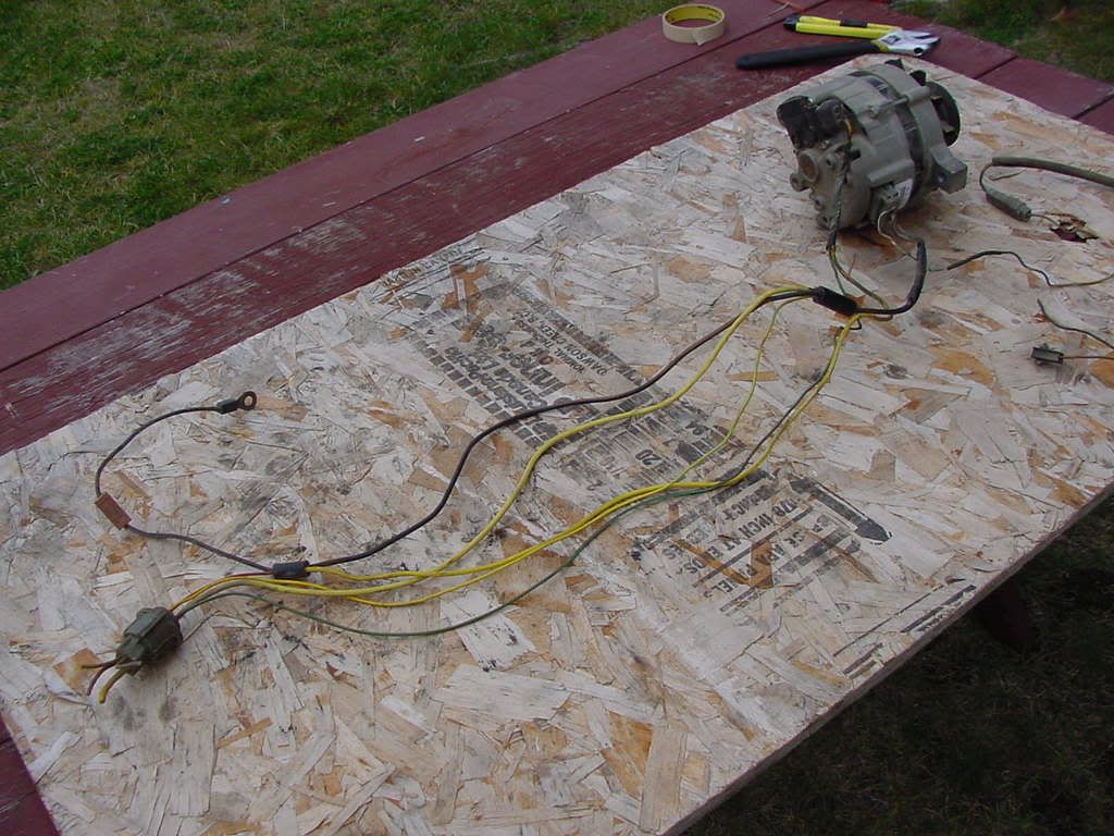
Here is a photo of my ALT harness showing the �shunt� (black looking wire) between the large black splices. The small wires off the splice points feed the amp meter.
.
I guess I would have to say current is �more� correct then voltage as far as what cause the needle to deflect. But in my mind it is easier for me to understand the concept as� applied voltage dropping across the internal resistance of the meter is what causes the current to flow internally in the meter movement. All of the resistances in the circuit are fixed and thus in my mind, the changing voltage across the shunt ends up causing the amp meter needle to move�while this analogy might be technically flawed� my mind just likes it better.
I guess I think you are both correct�.
Anyway moving on to the G3 ALT �upgrade�� I still have not installed the 3G ALT I recently got at the junk yard as I am frustrated with loosing the amp meter. I really don�t need the extra amps, I just don�t like my current fire hazard 2G ALT, and it�s also the worst designed ALT I have ever seen.
So I have thought about making my own shunt but I don�t know the currently installed amp meter �Rm and Ifs��. Here a good link to what I am talking about�.
http://www2.ece.ohio-state.edu/~fior...onvalMeter.pdf
I do plan on doing some bench testing with a ford amp meter at some point down the road.
Another idea would be to just de-rate the 3G with a 60 circuit breaker and using the current wiring harness/shunt. The only risk I can see with this plan is popping the CB with a totally dead battery and thus forcing me to idle the engine, to limit ALT amp output, until the battery is charged enough to draw less than say... 20amps.
Any thoughts�
Here is a photo of my ALT harness showing the �shunt� (black looking wire) between the large black splices. The small wires off the splice points feed the amp meter.
.
#22
11-16-2010, 12:49 PM
As far as your question, it shouldn't be too terribly hard to rig up your own shunt to make the factory ammeter work with a newer alternator. It would be nice to have one sitting on a bench to play with though.
Edit - Quick Google search tells me that I have a 1G alternator.... hopefully they are less fire prone
I am still curious about the inherent problems with the 2G.
#23
11-16-2010, 01:09 PM

Join Date: Jun 2005
Location: Temple, TX
Posts: 176
Likes: 0
Received 0 Likes
on
0 Posts
A lot of what lead me to ask the questions I did and want to move everything off the solenoid came from reading a couple of the articles on this site: http://www.madelectrical.com/electrical-tech.shtml<br /><br />
It's mostly based on GM stuff, but a lot of the same principles apply. It has good insight as to why the factory wired a lot of things the way they did...
It's mostly based on GM stuff, but a lot of the same principles apply. It has good insight as to why the factory wired a lot of things the way they did...
#24
11-16-2010, 02:33 PM
While we are talking about ammeters, is it just me or do they rarely move? I've driven a lot of different vehicles with ammeters and I've only seen a few of them move at all.
I've had my 77 F-150 4x4 since 2005 and all this time I thought the ammeter did not work at all. About a month ago I was trying to get a 1977 Ranger XLT 2wd running that I had just bought. I hooked cables up to it from my 4x4 with the engine not running. I had cranked the Ranger over quite a bit without starting my 4x4. When I finally started the 4x4 that I had been running the battery down on- the Ammeter was showing output! I could not believe it, first time I've seen it move in 5 years!
I've also had a bunch of 79 to 86 Mustangs with ammeters, they rarely move as well. The one on my 85 GT never moved until I put underdrive pulleys on it. Then if the car idled with high electrical loads on it then I raise the RPM it will show output. I never saw much use for the factory ammeters since none of them I have seen hardly ever move! I definitely prefer a factory volt gauge that the Mustang got in 87. I also run an autometer volt gauge in my truck.
Good read in this thread regardless.
#25
11-16-2010, 02:36 PM
What is so fundamentally flawed about the 2G design? You say it's fire prone, where does that come from? Not saying you're wrong by any means, I've just never looked into it at all.
As far as your question, it shouldn't be too terribly hard to rig up your own shunt to make the factory ammeter work with a newer alternator. It would be nice to have one sitting on a bench to play with though.
Edit - Quick Google search tells me that I have a 1G alternator.... hopefully they are less fire prone I am still curious about the inherent problems with the 2G.
As far as your question, it shouldn't be too terribly hard to rig up your own shunt to make the factory ammeter work with a newer alternator. It would be nice to have one sitting on a bench to play with though.
Edit - Quick Google search tells me that I have a 1G alternator.... hopefully they are less fire prone
I am still curious about the inherent problems with the 2G.<O
 </O
</Ohttps://www.ford-trucks.com/forums/318948-f250-alternator-almost-burned.html
<O
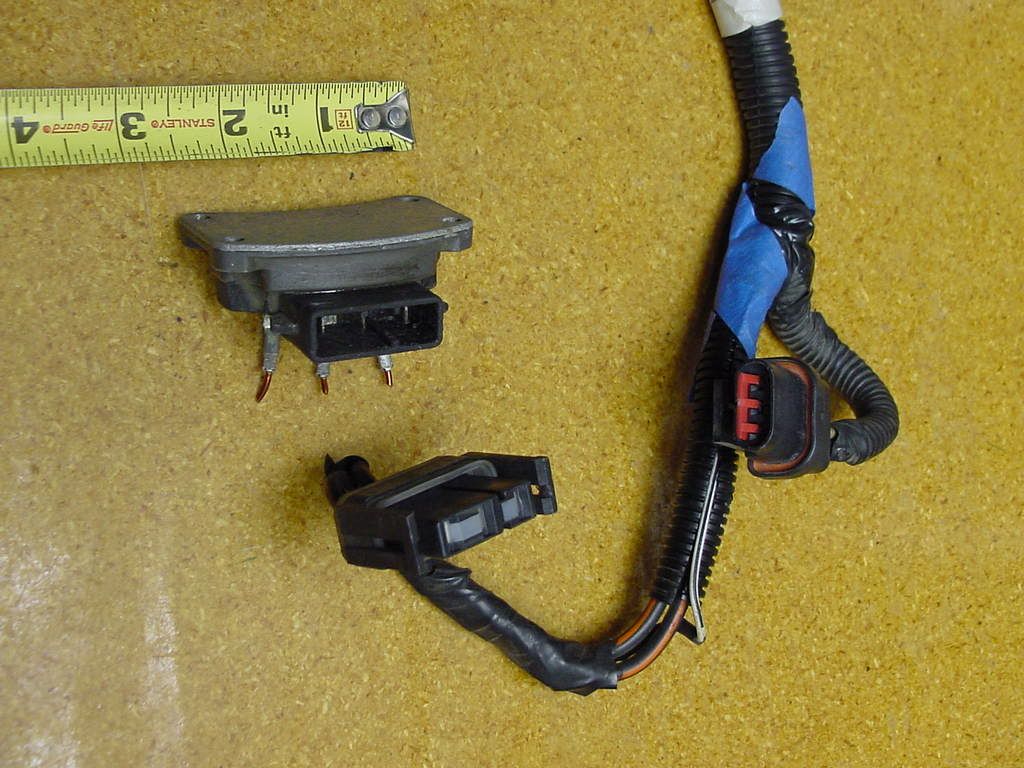
</OThe rectifier assembly was also reduced in size with only 1 heat sink point for both the power connector and the diode rectifier assembly, here is a photo of it�
.
#26
11-16-2010, 02:36 PM
Well, if everything is working properly you shouldn't see it move too much. Go press the brake pedal and you'll see it flinch ever so slightly towards discharge. Turn on your lights, etc, and it will get more. Leave your lights on for a while then start it up and you'll see it'll charge pretty heavy then taper off to near nothing.
#27
11-16-2010, 02:38 PM
I am curious. I found a website that sells 100amp upgrades for $69. I wonder, if being externally regulated, you could get by with one of those kits because there is sufficient cooling capacity or if it would just get too hot and fry itself?
#28
11-16-2010, 04:24 PM
BUT� putting it in a 60 amp ALT does not mean it will change the ALT to a 100 amp ALT, it is still a 60 amp ALT with better parts inside.
Really not sure of what �upgrade� you are looking at, but if you truly need more power than your current ALT can provide you should look into a 3G ALT. But before you go down that road you should ask yourself do you really NEED more amps� or just want a more powerful ALT.
Jim
#29
11-16-2010, 04:31 PM
Well you have to understand first of all that I like to tinker. I'm always looking for information about what can be upgraded and how and for what cost. I may end up doing an upgrade post haste or I may not. It depends as you say on the need vs desire, cost, etc.
In my case I will not know if I need a higher output alternator until I get all of my accessories installed, the biggest being an electric fan. Before I can install the electric fan, I will have to own one. It's one of those items on my Christmas list that may come, may not. I want one, and I think it would really help my fuel economy, but I don't NEED one so if I don't get one for Christmas, I don't know when I'll get one. Now with that being said, any upgrades that I do, I want to still work with the factory ammeter. I absolutely HATE having a dead gauge on a cluster, it seems so ghetto to me. Thus, replacing the alternator or upgrading the internals while maintaining stock connectivity is a big plus to me. True it might not put out 100 amps, but say I end up drawing 65 amps. Surely the 100 amp upgrade inside the 60 would give me the overhead for 5 amps. I don't need to light up the city, I just don't need it to severely discharge in a worst case type scenario.
Make sense?
Oh, to answer your question, the upgrade kit includes a 105am stator along with the upgraded rectifier and such.
#30
11-16-2010, 04:46 PM
Join Date: Jun 2005
Location: Temple, TX
Posts: 176
Likes: 0
Received 0 Likes
on
0 Posts
Nathan, FWIW, I'm running a parts store reman 60 amp alternator. Idling at 800 rpm with my MSD ignition system, big Holley fuel pump, and Lincoln MK8 fan all running, it still maintains about 14.1v at the battery. Now that I think about it I wish I'd checked with the headlights on as well, but I still think that's a good indication that the little 60 amp alt is more capable than we tend to give it credit for.