HIGH IDLE ???
#1
 10-24-2010, 09:41 AM

Join Date: Oct 2006
Location: calgary,ab,canada
Posts: 42
Likes: 0
Received 0 Likes
on
0 Posts
HIGH IDLE ???
Was reading the owners manual on the high idle and it says you have to have the E - brake applied for it to come on automaticaly. Bad news for us people who live in the north. You just cant afford to take a chance at 35 below an dend up with afrozen E- brake cable!!! Hoping someone might know how to bypass this. By the way I have now upliffter switches.
#2
10-24-2010, 02:52 PM

SEIC has always required the e-brake since 2005 at least.
SVE bulletin Q-108 for 2005 confirms the parking brake is required.
I don't know what model you owned previously so that could have an impact and I don't know how it worked previously to MY2005.
The only changes I'm aware of is with the 6.0, owners could leave the SEIC switch on and regulate high idle using the e-brake. With the 6.4 and 6.7, leaving the SEIC switch on will not allow the DPF to regen (so I've read) so now it's a two step process.
#4
10-24-2010, 05:21 PM

You know, I've been racking my brain on this. I am 99% sure that the cold weather strategy for the elevated idle will work even if the parking brake is not engaged. I had a 6.4 ('08) and I swear that during cold weather the PCM would elevate the idle regardless of parking brake position, as long as the truck was in "P" for park on the gear selector.
Now, if you wire a 12V source to the PTO or SEIC wire under the dash, you will need the parking brake engaged.
My new 6.7 has not experienced cold weather yet so I cannot confirm on these new trucks but I would bet it's the same as the 6.4.
Now, if you wire a 12V source to the PTO or SEIC wire under the dash, you will need the parking brake engaged.
My new 6.7 has not experienced cold weather yet so I cannot confirm on these new trucks but I would bet it's the same as the 6.4.
#5
10-24-2010, 10:13 PM
#7
10-28-2010, 04:24 PM

Trending Topics
#8
10-28-2010, 04:35 PM
All the info you need is right here:
https://www.fleet.ford.com/truckbbas...tml/Q180-A.pdf
Specifically, there is a chart "B" that gives you resistor values for target RPM.
https://www.fleet.ford.com/truckbbas...tml/Q180-A.pdf
Specifically, there is a chart "B" that gives you resistor values for target RPM.
#9
10-28-2010, 04:44 PM
Yes I saw that and printed it out. The resistor I am wanting to use is 20K but its not available. I can only find a 22K. The question I have is am I using the correct wires? The SEIC pdf that I read refers to a bundle of 4 wires which includes the SEIC and PTO wires. I can't find such a bundle. Just the the pigtail of a bunch of wires. I also read that the SEIC wire was the YELLOW/GREEN wire.
I found one but I am not sure that its the correct one.
I found one but I am not sure that its the correct one.
#10
10-28-2010, 04:47 PM
#11
10-28-2010, 10:28 PM
PROBLEM SOLVED!!!!!!!!!!!!!!
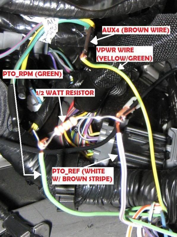
Need to connect the YELLOW/GREEN DIRECTLY TO THE AUX SWITCH
Then connect PTO_REF (WHITE WIRE WITH BROWN STRIPE) to PTO_RPM (GREEN WIRE) WITH A RESISTOR BETWEEN THEM. Works like a charm!!!
I was using the WRONG (BROWN/WHITE) WIRE!!
NOTE!!!!!
There is a BROWN WIRE WITH WHITE STRIPE.....NOT THE RIGHT WIRE!
USE THE WHITE WIRE WITH BROWN STRIPE!!!!!!

#13
10-28-2010, 10:49 PM
Junior User
Join Date: Sep 2010
Location: Alberta, Canada
Posts: 67
Likes: 0
Received 0 Likes
on
0 Posts
PROBLEM SOLVED!!!!!!!!!!!!!!
Need to connect the GREEN AND YELLOW DIRECTLY TO THE AUX SWITCH
Then connect PTO_REF (WHITE WIRE WITH BROWN STRIPE) to PTO_RPM (GREEN WIRE) WITH A RESISTOR BETWEEN THEM. Works like a charm!!!
I was using the WRONG (BROWN/WHITE) WIRE!!
NOTE!!!!!
There is a BROWN WIRE WITH WHITE STRIPE.....NOT THE RIGHT WIRE!
USE THE WHITE WIRE WITH BROWN STRIPE!!!!!!
INPUT (VPWR)
PTO
REQUEST1
PCM Pin C1232B-6 Circuit No. CE912 Wire Color: Yellow / Green
• Applying vehicle battery voltage to this wire begins SEIC process.
• Signals TorqShift™ transmission to enter SEIC strategy.
• Verifies safety enablers.
• Turns off OBD and other emission-related monitoring.
• Elevates engine speed to target found at PTO-RPM circuit.
• Invokes the PTO relay circuit when safety enablers are met.
• Looks for the target engine speed requested at the PTO_RPM circuit using a resistor or POT.
That's great!! Just want to make sure your two posts above should say "Yellow/Green". The picture above show's "Yellow/Green" wire correct?
Rick

